Overview
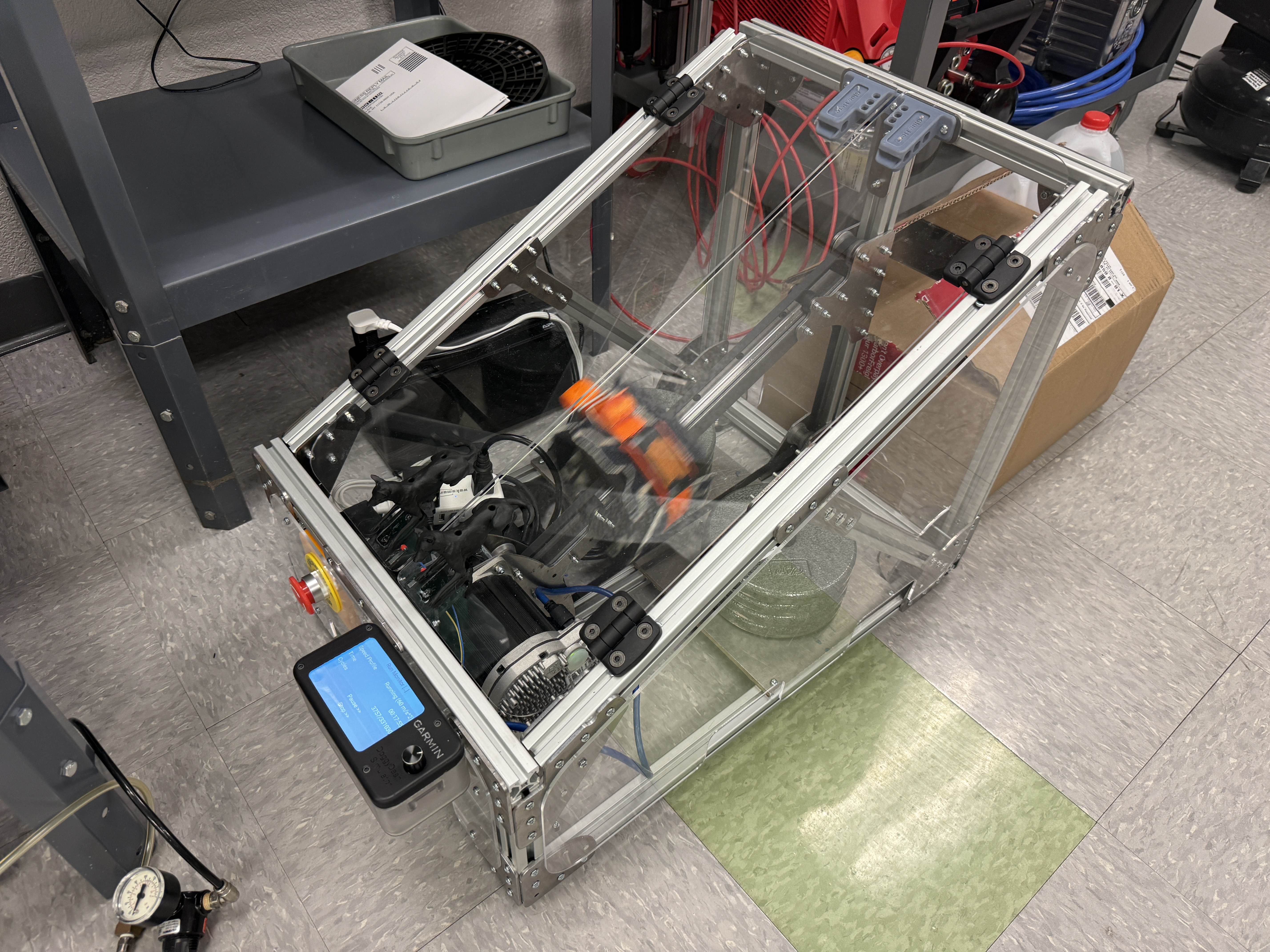
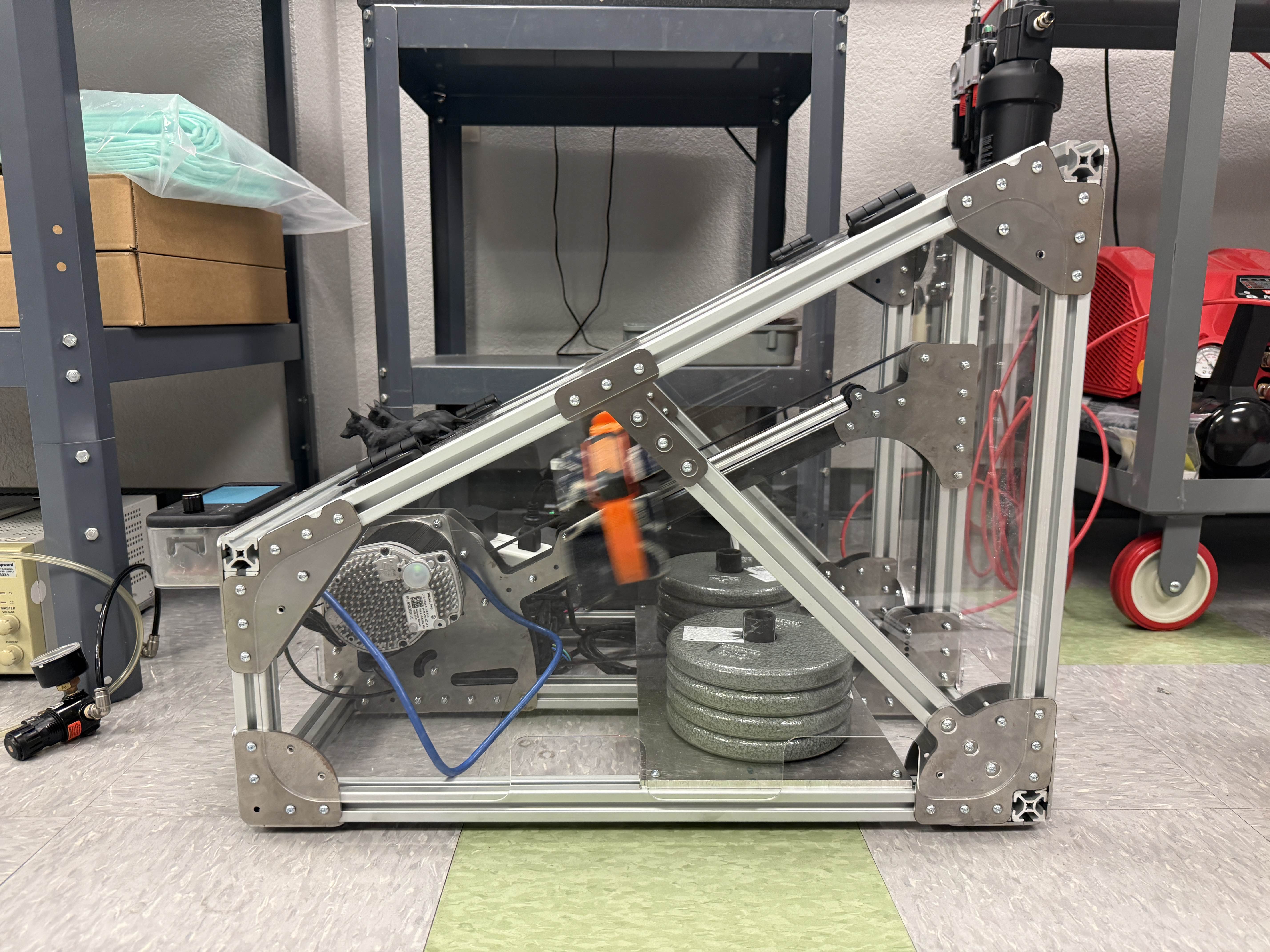
I was the sole project owner of an electromechanical test rig for dog devices, designed to simulate a hunting dog running at full speed. I designed the rig to automate testing while using a modular neck system to accommodate different dog sizes. Over 12 weeks, I handled data collection, CAD, electrical design, software architecture, and documentation, and deployed the test rig at the end of my internship.
Approach
When I started this project, I had no idea how to build a dog simulator. I first needed to understand how dogs actually run, such as the forces on their necks and the path their neck follows through space. I needed data.
I used a multimodal approach to gather data. First, I built an OpenCV (computer vision) program to track the dog's neck in fixed frame of reference videos, like footage of a dog running on a trampoline. This gave me a rough trajectory of the dog's neck through space. I then attached a 100 Hz accelerometer to a coworker's dog to measure neck acceleration during a full speed sprint.
An FFT revealed frequencies above the Nyquist frequency, meaning the data was being aliased. I switched to 1000 Hz sampling, which eliminated the aliasing and gave me reliable acceleration data to design the test rig around.
There were a few requirements for the simulator, which drove the following design choices:
Strict safety requirements
- Enclosed the simulator in acrylic panels to isolate users from moving components
- Added door sensors that stop motor movement when doors were opened
- Added an accessible E-stop that cuts power to the entire system
- Used rubber damping feet and added weights to prevent the simulator from walking
- Implemented a homing process for the motor
Track cycles completed
- Used a Teensy 3.6 to control the industrial servo motor
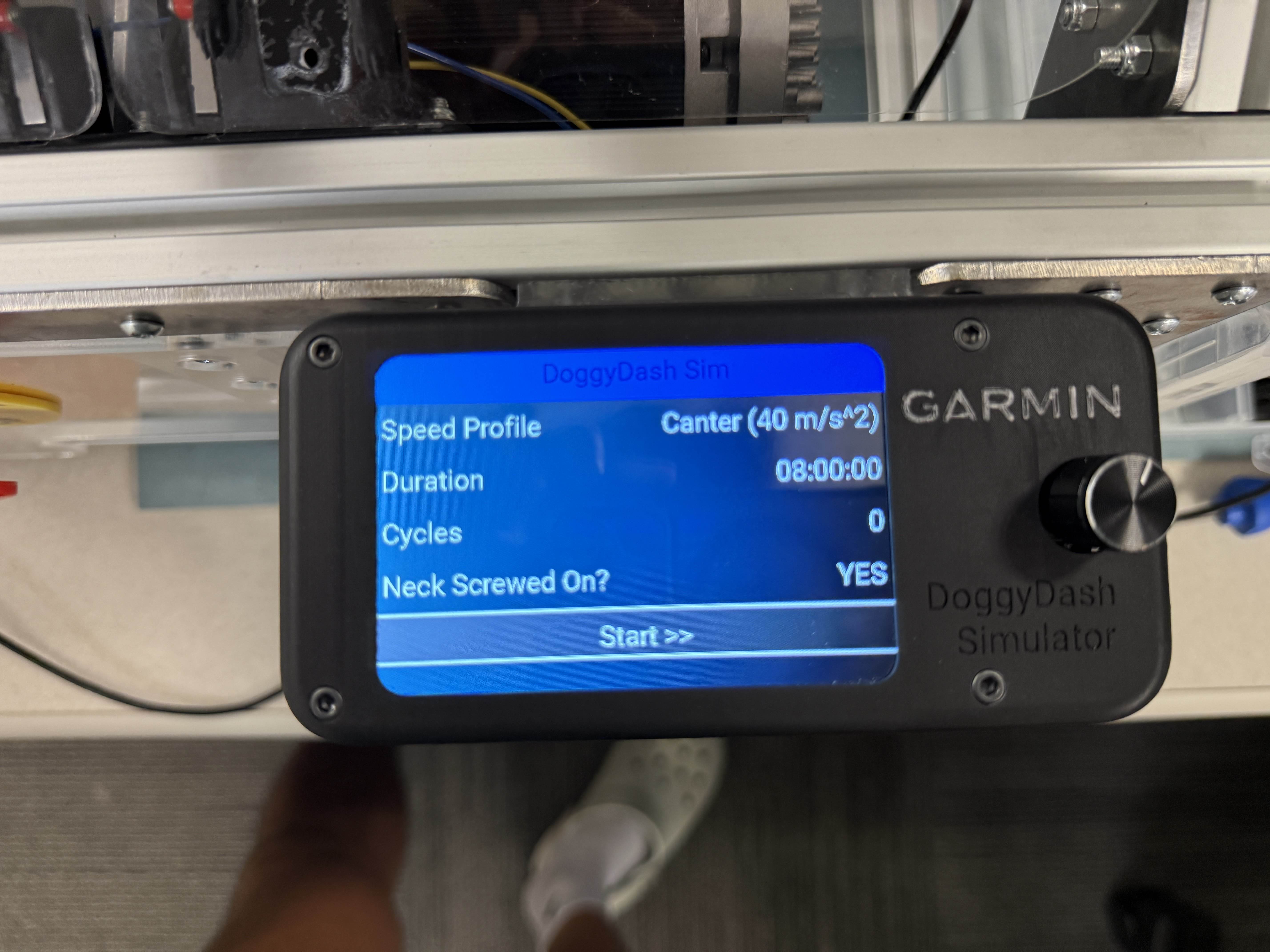
- Built a UI that allows users to set cycle duration and automatically tracks completed cycles
Adjustable neck circumference and gait speed
- Designed 3 interchangeable neck sizes for small, medium, and large dogs. The necks can be easily swapped out with 4 screws
- Calculated velocity and acceleration profiles for walking, cantering, and running, then integrated them into the UI
$2500 budget
- Created a tabulated order form and used design reviews to reduce cost
- Used cost-efficient materials such as aluminum extrusions and sheet metal brackets
Engineering Process
I started with hand calculations for motor torque, velocity, acceleration, and the structural loads on the motion and support components. From there, I selected the electrical components while developing the full simulator in CAD. I held design reviews throughout the process to get feedback on the mechanical, electrical, and software subsystems before moving into fabrication.
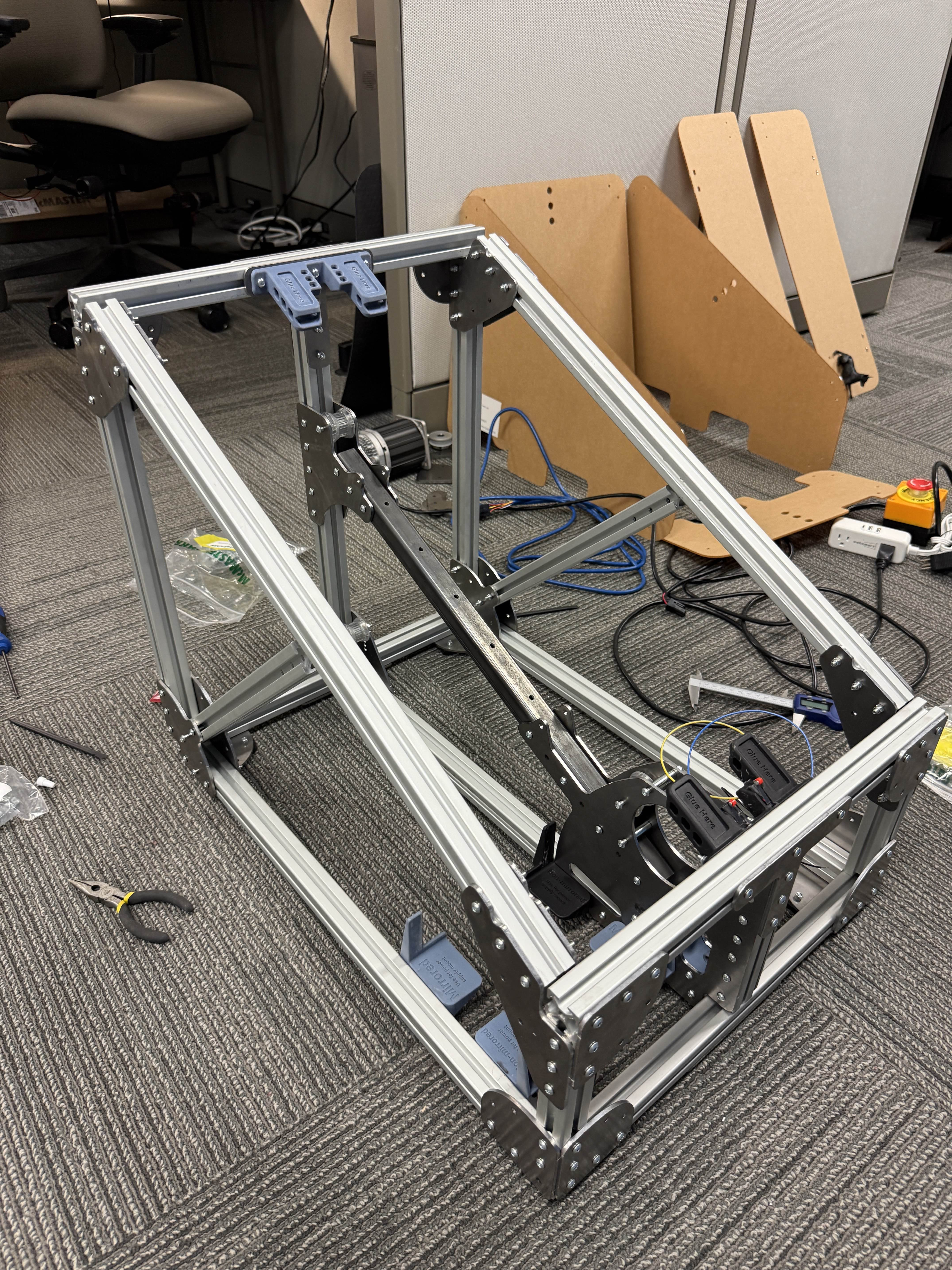
Once the parts arrived, I built the simulator, soldered the electrical peripherals, and troubleshot the system. After a microcontroller compatibility issue forced a hardware change, an intern teammate and I rebuilt the electrical harness. Once the electrical system was complete, my teammate developed the simulator software while we tuned the system and debugged it together.
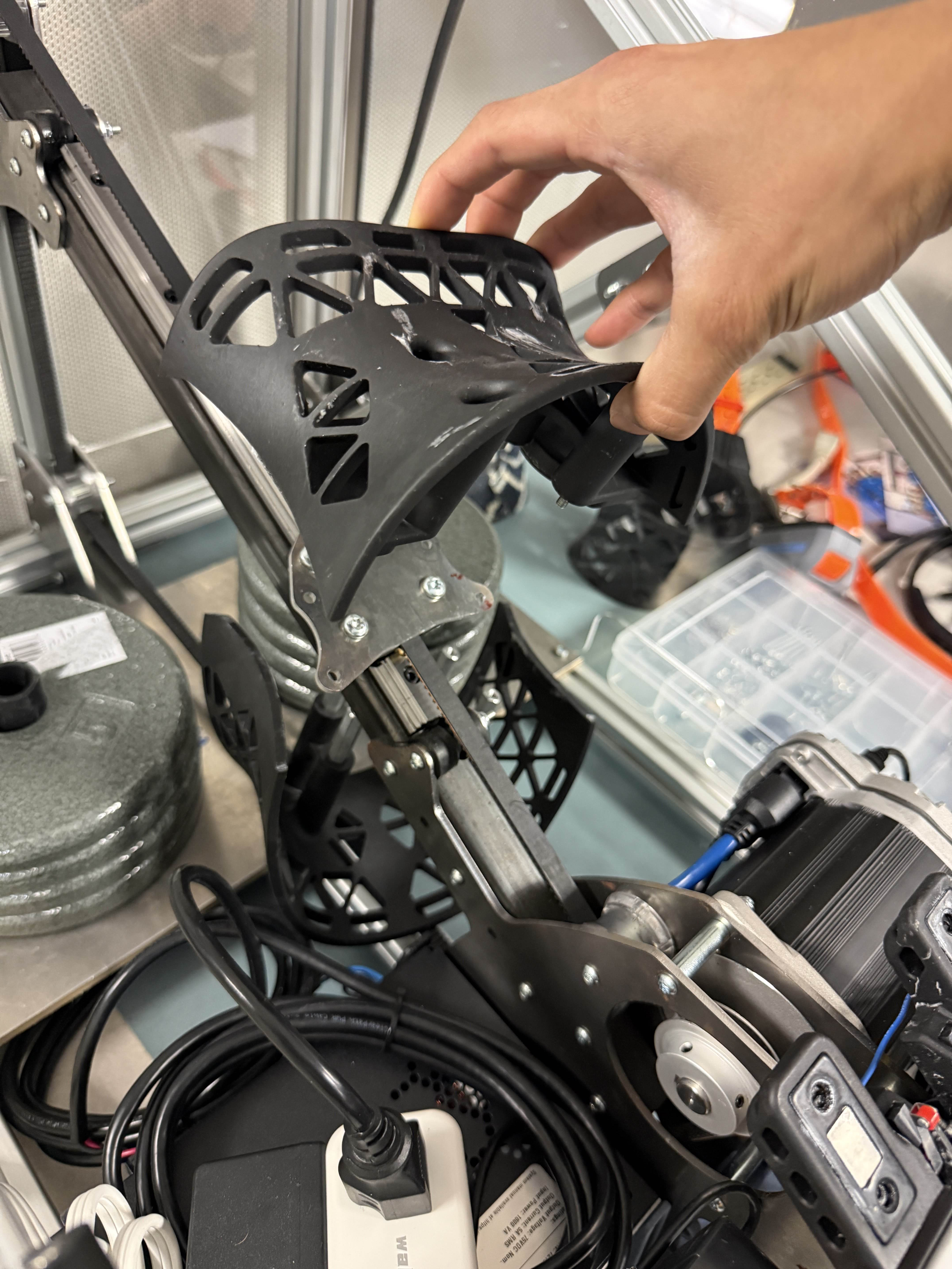
Before leaving, I validated the system with the same accelerometer data collection, and determined that the acceleration of the dog simulator was 92% similar to the real dog in acceleration magnitude. I documented the entire system in detail, including the mechanical, electrical, and software designs, so other engineers could troubleshoot, repair, and reproduce the simulator if needed.
What I learned
This internship taught me a lot about mechanical product design, fast iteration, quickly pivoting designs, documentation, embedded systems, power architecture, and how software brings everything together. I got to experience the full product development cycle firsthand while also learning how Garmin develops products at scale. I gained a deeper understanding of injection molding and large-scale manufacturing, as well as how each engineering team contributes to building a successful product.