Overview
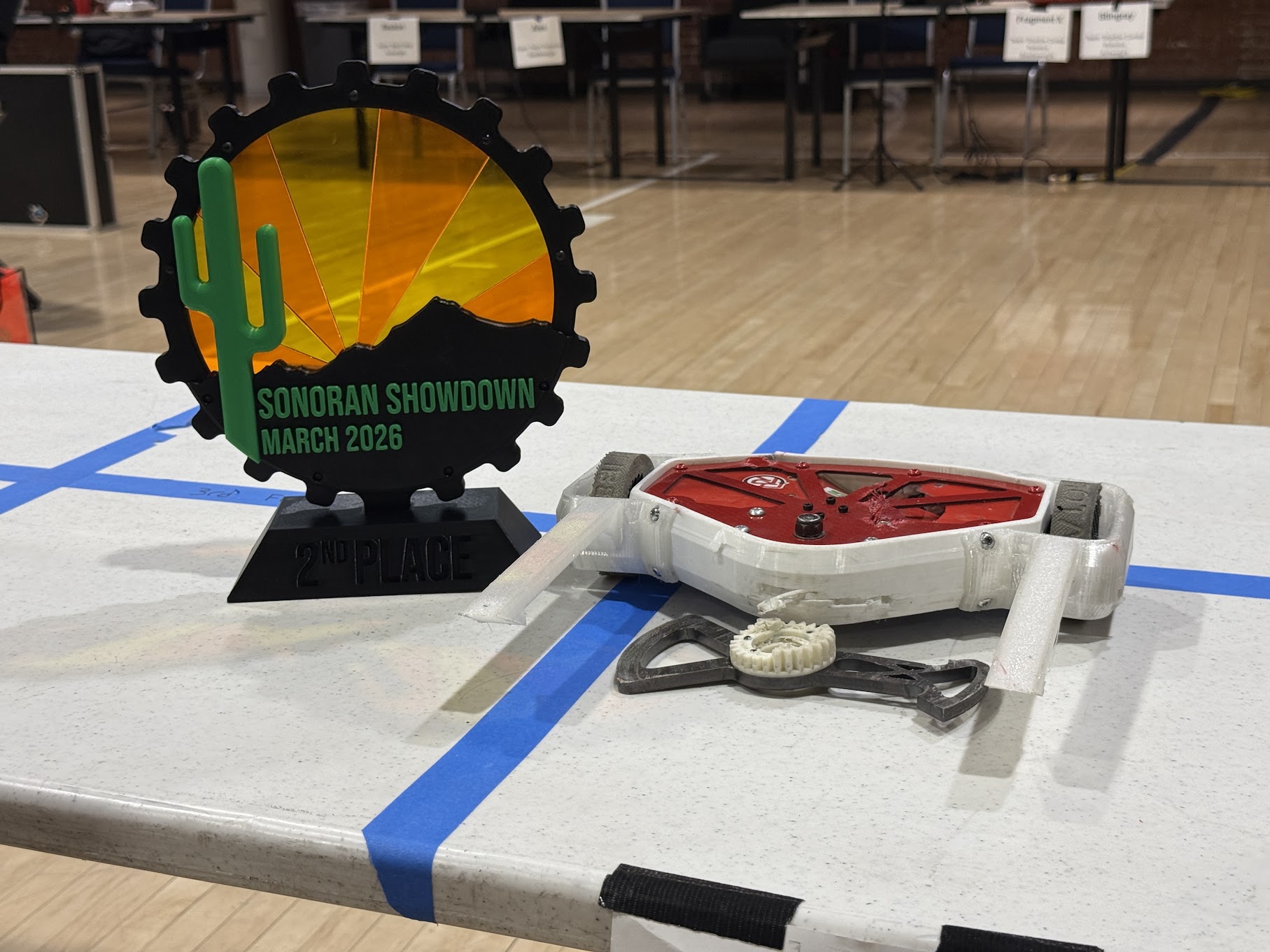
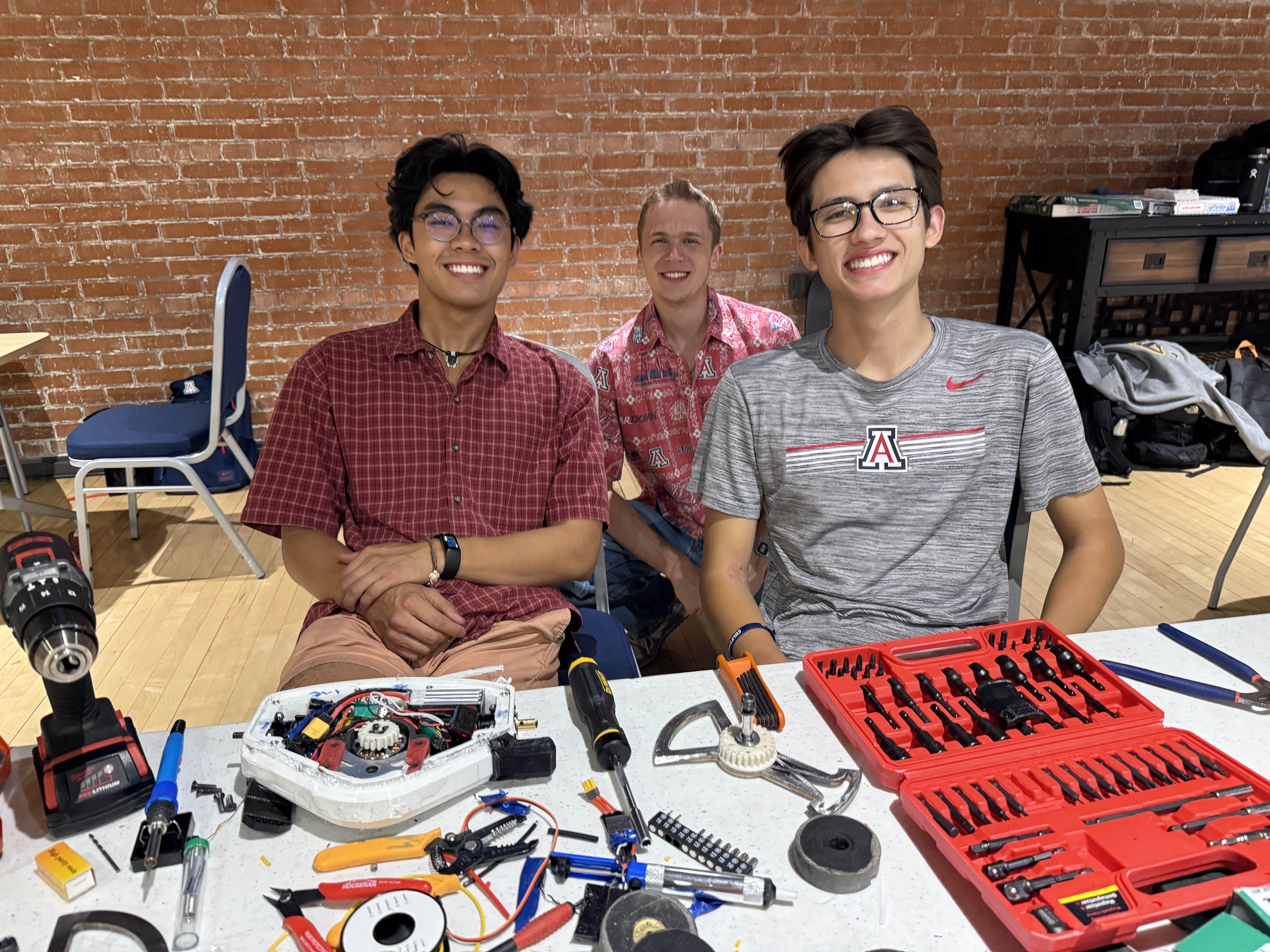
I started working on this combat robot during my freshman year of college, and I've kept iterating it ever since. I designed the first version from scratch, and over the years, my team and I have improved it through countless redesigns, repairs, and competitions. We’ve taken it to the podium at several Arizona tournaments and competed at a national competition twice.
As I’ve learned more about combat robotics, I’ve continued tweaking the chassis, weapon, drivetrain, and electrical systems to make the robot more reliable and hard-hitting. My team and I have stopped actively developing it, and have since moved on to more ambitious projects, but we still maintain this robot and bring it to competitions.
Design Process
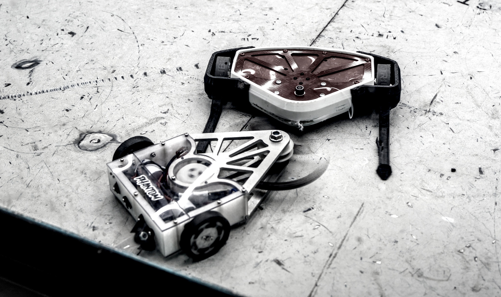
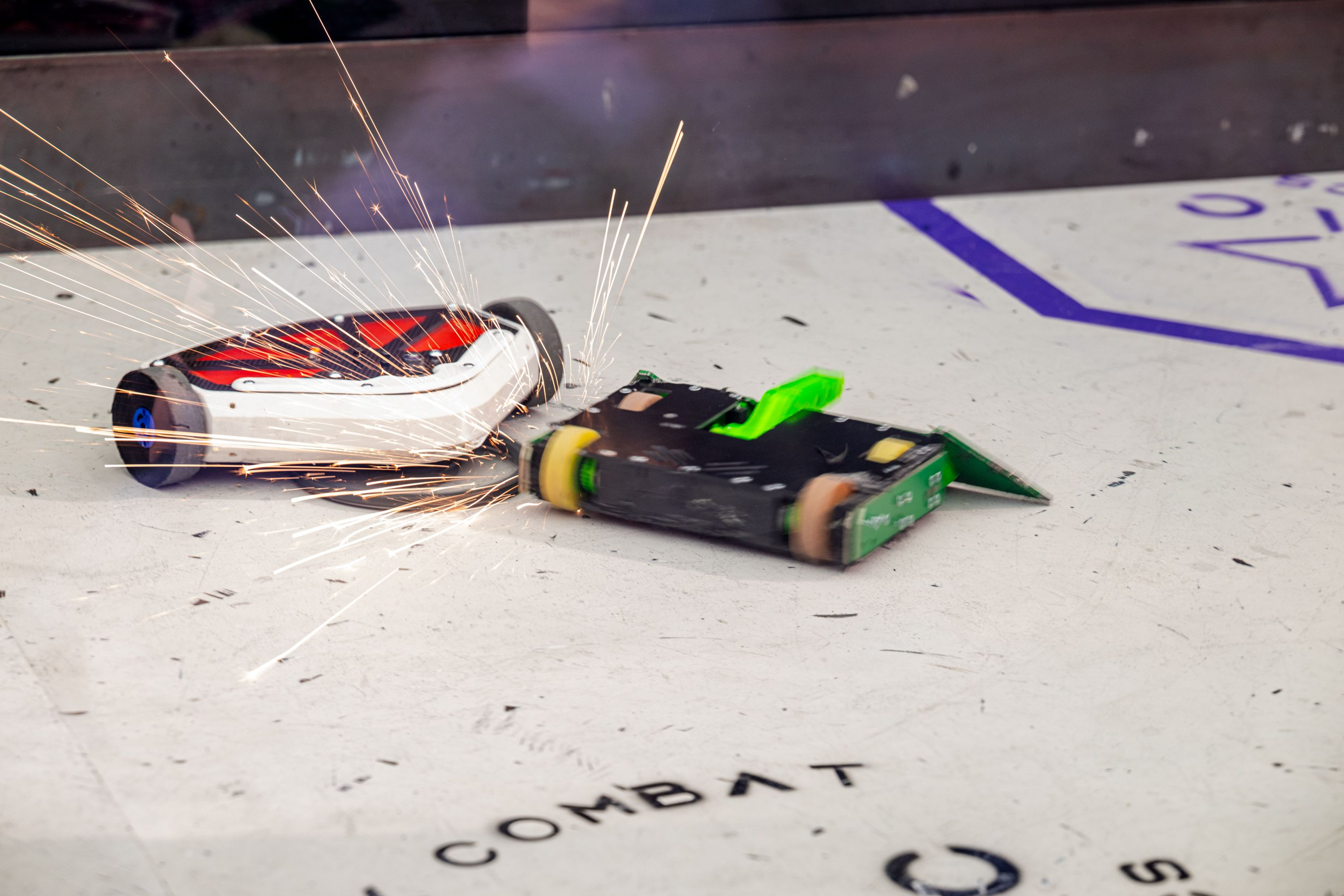
We started by creating a decision matrix to narrow down which robot archetype we wanted to build. We also wanted something that would be fun to drive and a little different from the typical designs. In the end, we chose an undercutter, a horizontally spinning blade mounted close to the ground. We liked how aggressive the design was and how it could attack an opponent's wheels and cut off their movement.
Starting out (Liberator MK1)
For the chassis, we chose UHMW, a slippery plastic that tends to chunk off when damaged instead of cracking. We used basic foam wheels and a pulley-driven weapon attached to a 1/8" AR500 steel blade. An aluminum hub connected the blade to the weapon motor, while aluminum plates sandwiched the assembly together and provided the structural rigidity needed to hold the UHMW midframe.
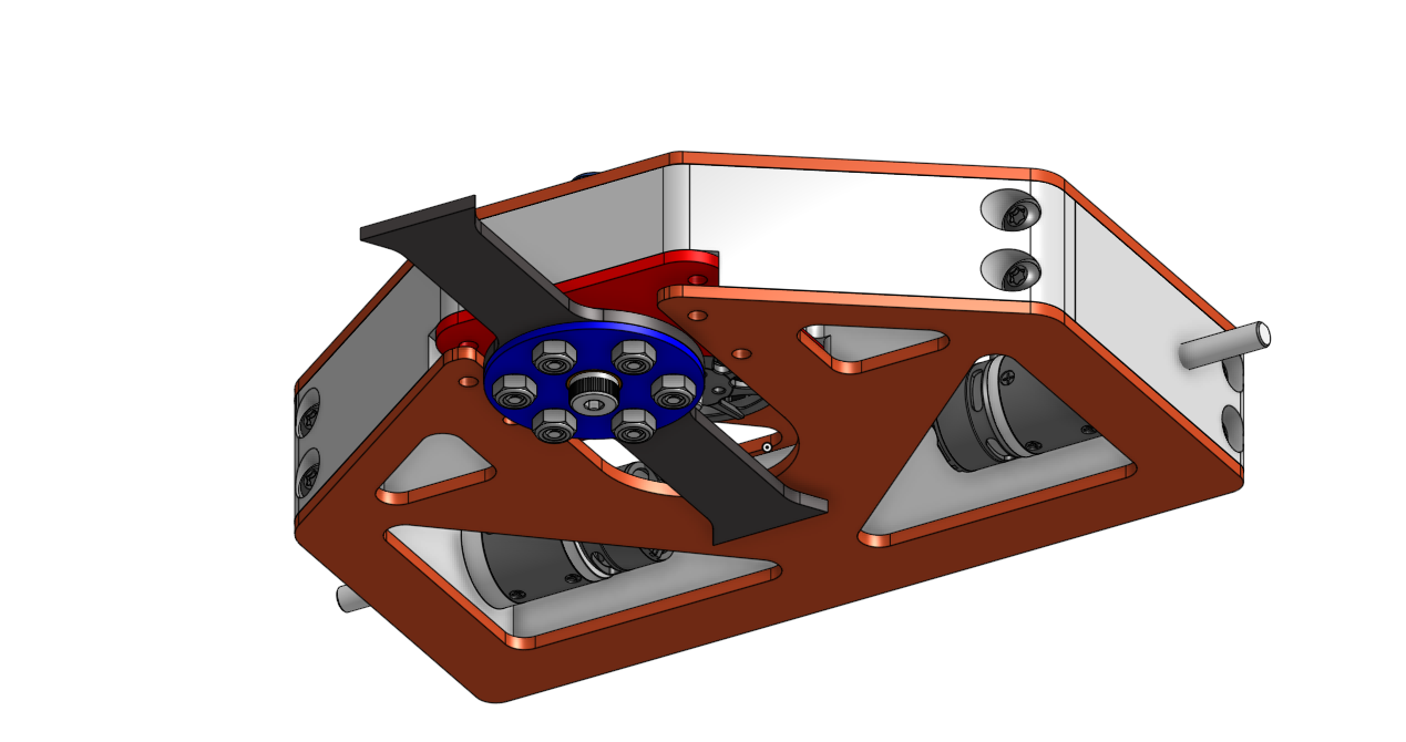
Once the parts arrived, we started assembling and soldering everything together. We quickly ran into issues fitting all of the electronics alongside the battery, and the overall assembly process was difficult because I was still learning how to design for manufacturing and assembly. We also struggled with being over the 3lb weight limit, which we fixed by drilling holes into our aluminum rails.
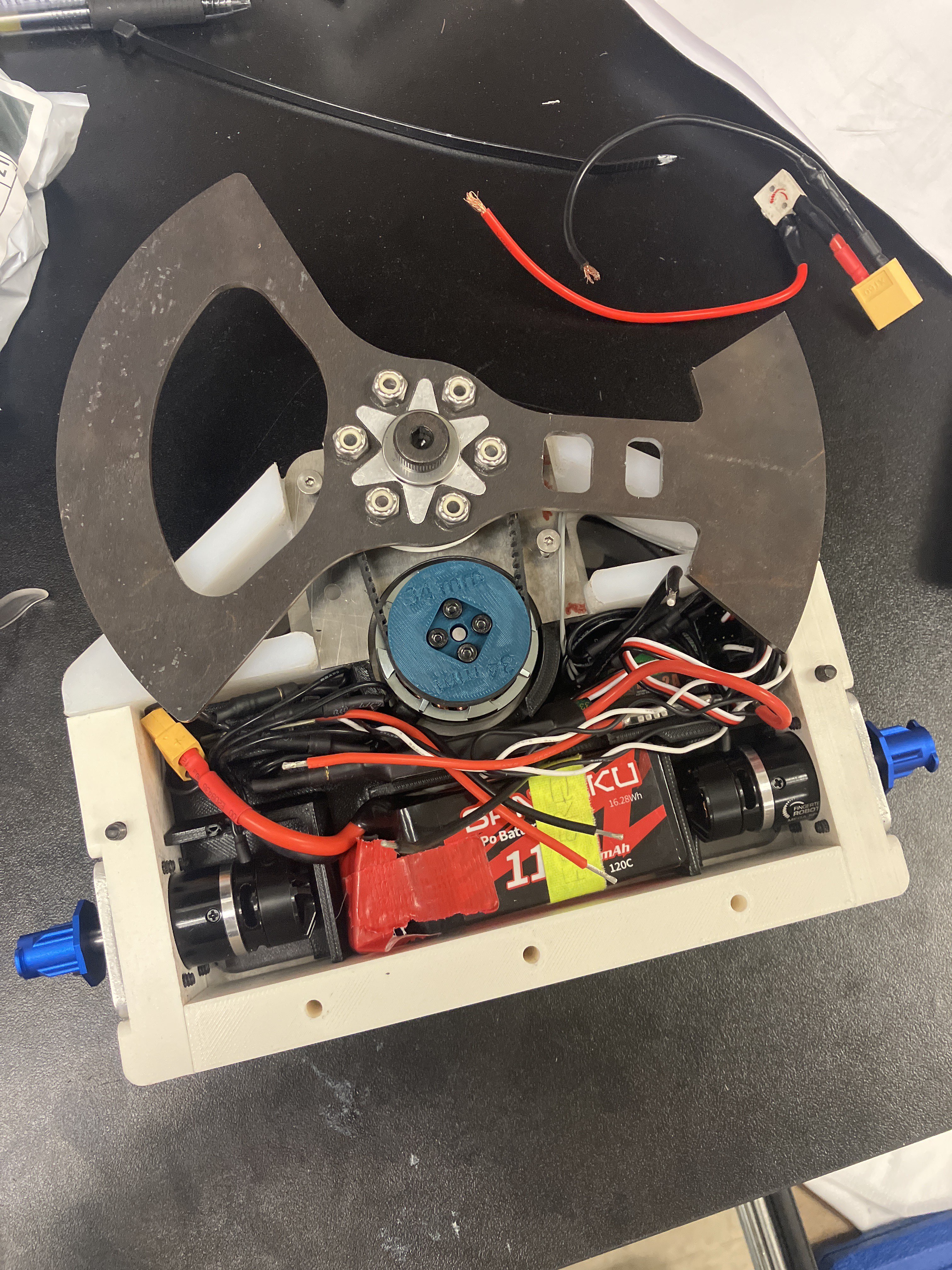
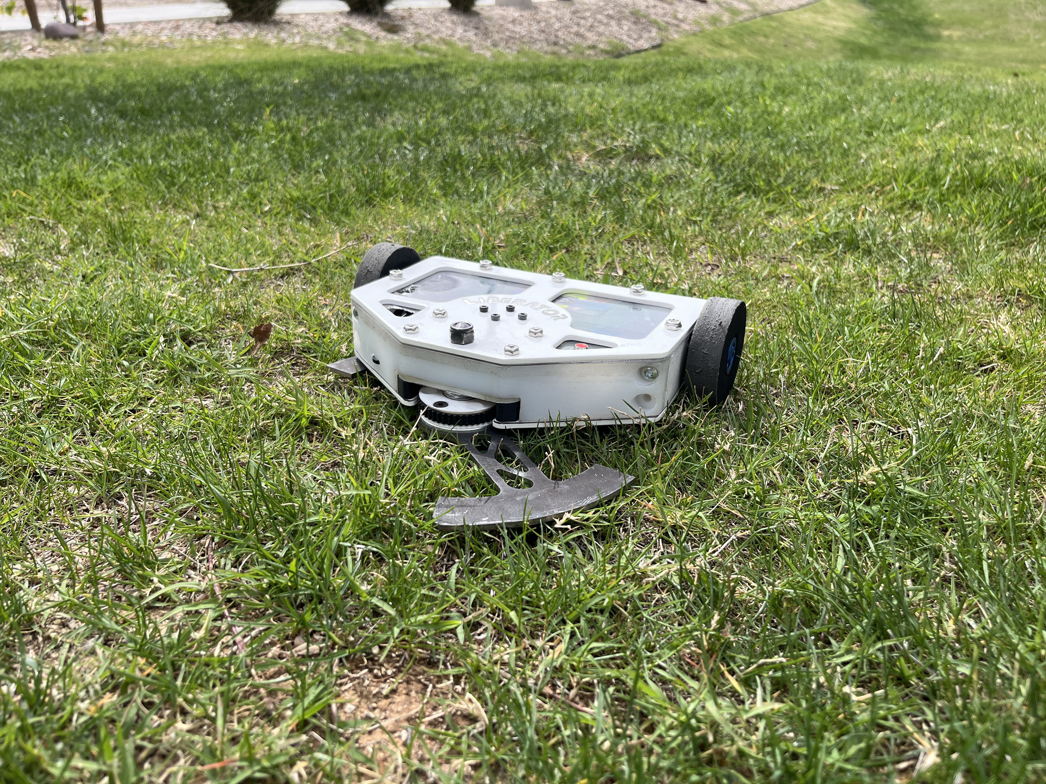
After the competition, we realized we had several major problems:
- The blade was too thin and its geometry was too weak. The 1/8" blade would bend upward on big hits and strike the chassis.
- The pulleys were implemented badly because the belt would melt and fall off.
- The chassis materials needed to be lighter, more ablative, and cheaper to manufacture.
- We needed more powerful motors and ESCs to prevent brownouts and improve performance.
- We had put far too much weight into the chassis, leaving less weight available for electronics, the weapon, and different armor packages.
We tried to iterate on the MK1 design by switching to a TPU mid-chassis, but there were so many changes we wanted to make that we decided to redesign the entire robot.
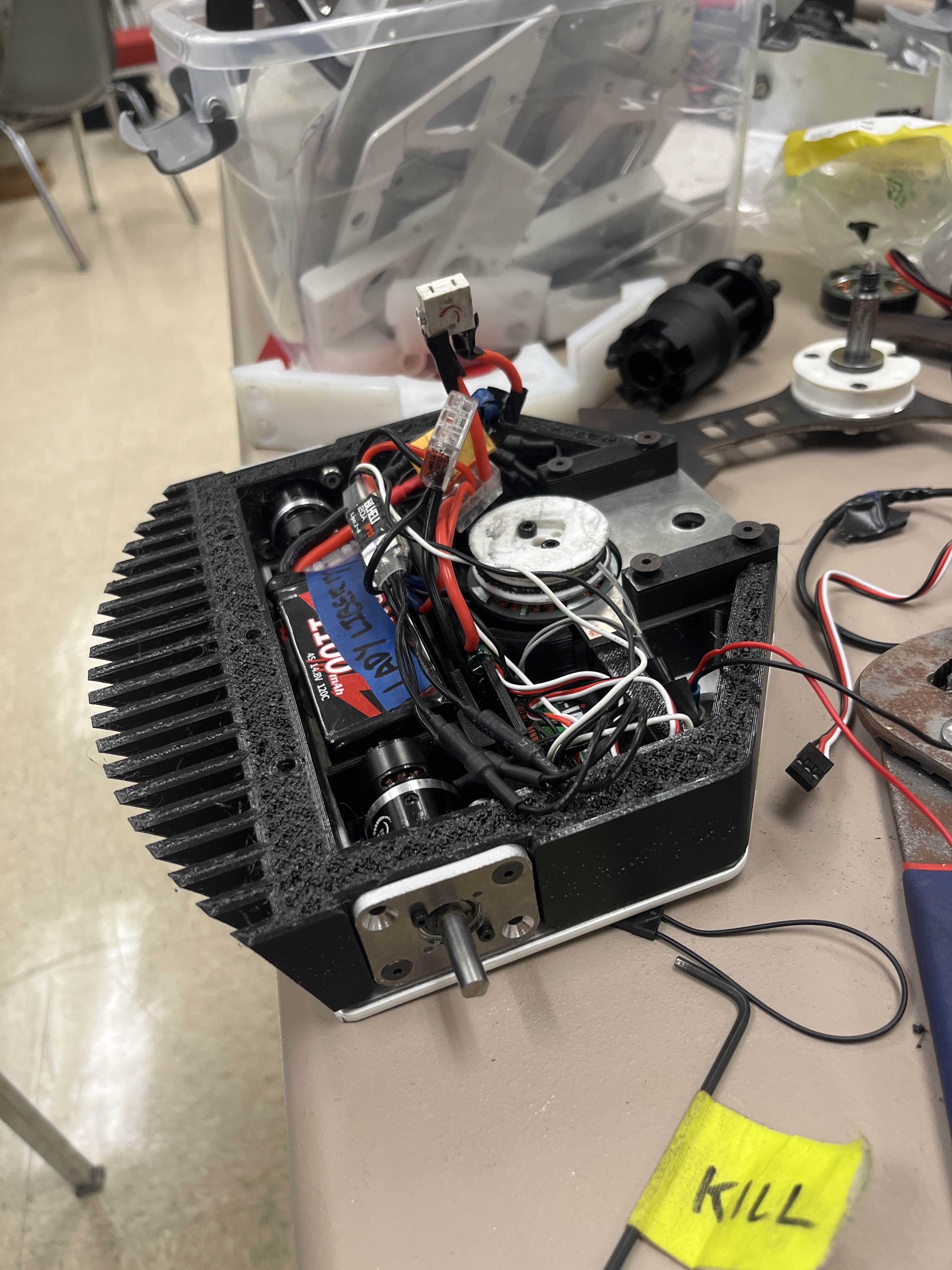
Fixing the Problems (Liberator MK2)
The next version came together over two years during my sophomore and junior years. We took everything we learned from MK1 and used it to rethink nearly every part of the robot.
Weapon System
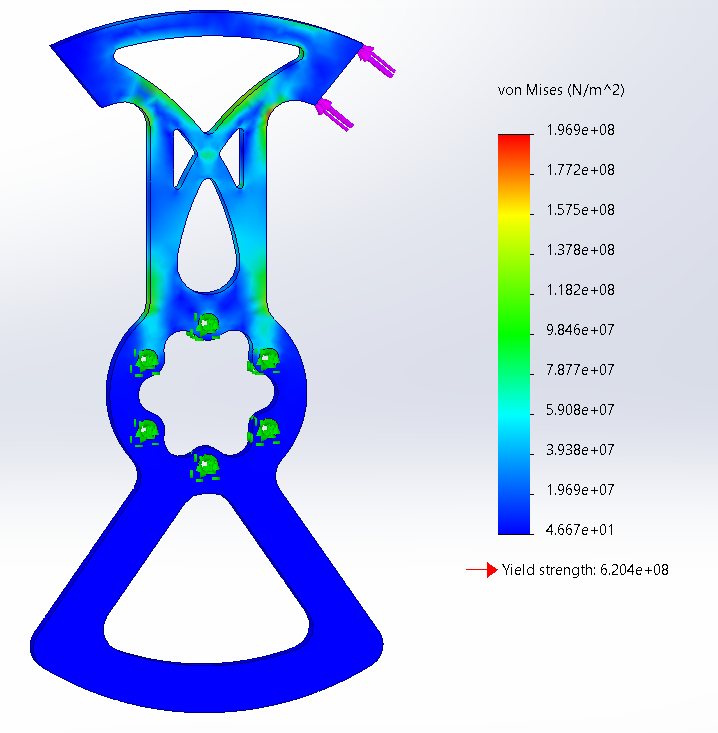
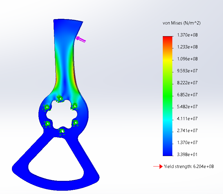
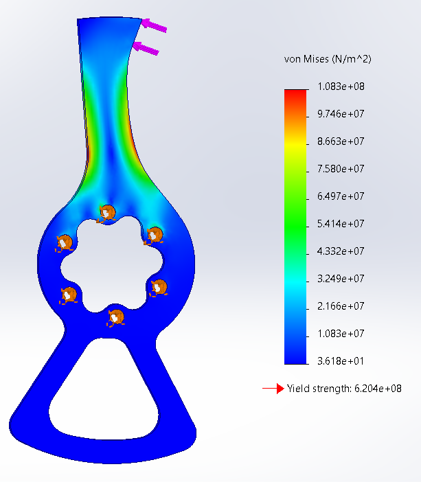
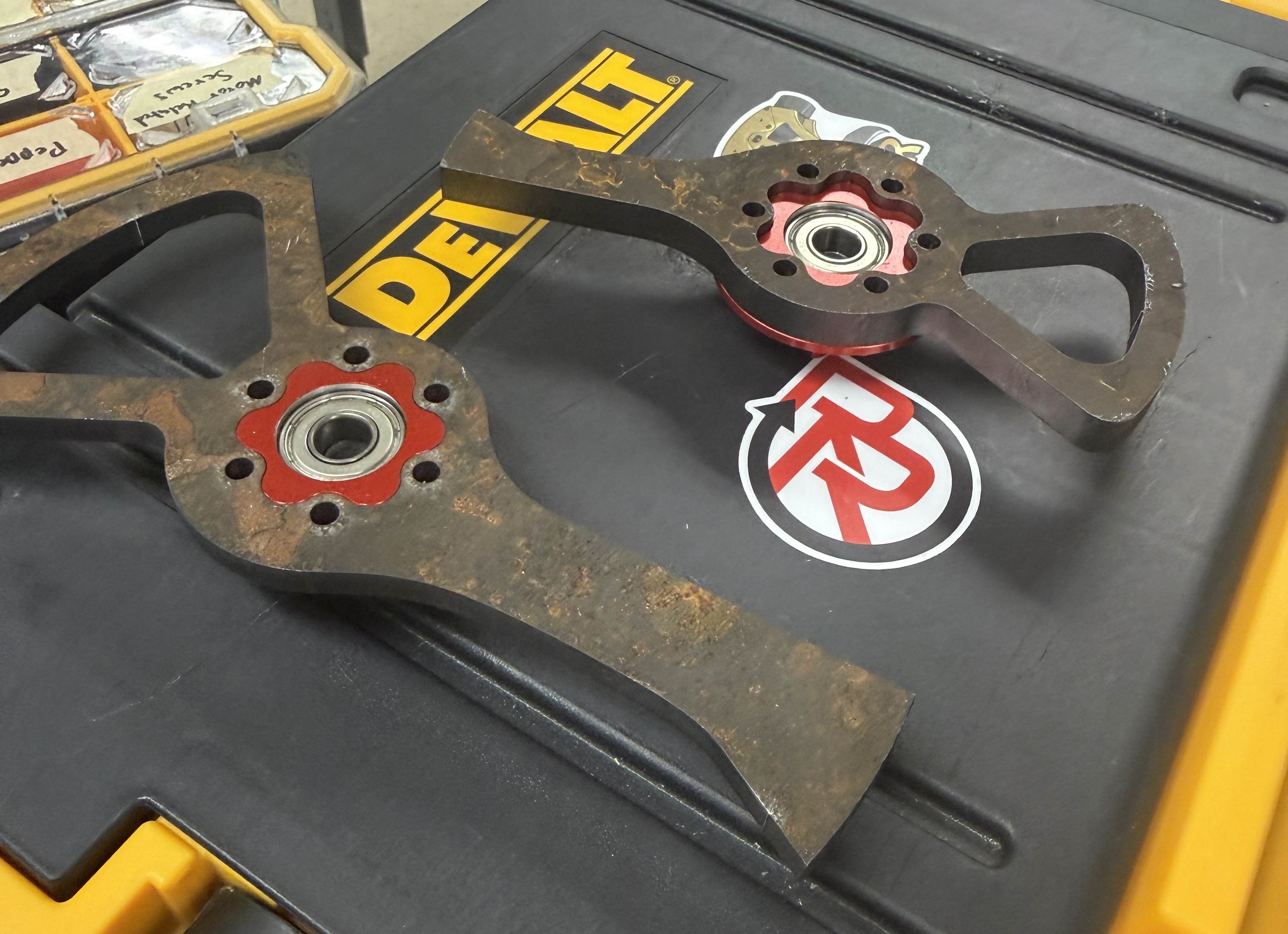
We increased the blade thickness to 1/4" AR500 and ran several analyses on the geometry to optimize its weight. I then used FEA to identify stress concentrations and improve the load paths. We also adjusted the key pattern to increase the steel thickness around the hub, where the bending moment was highest, while keeping the smooth spline that transferred shear loads into the hub.
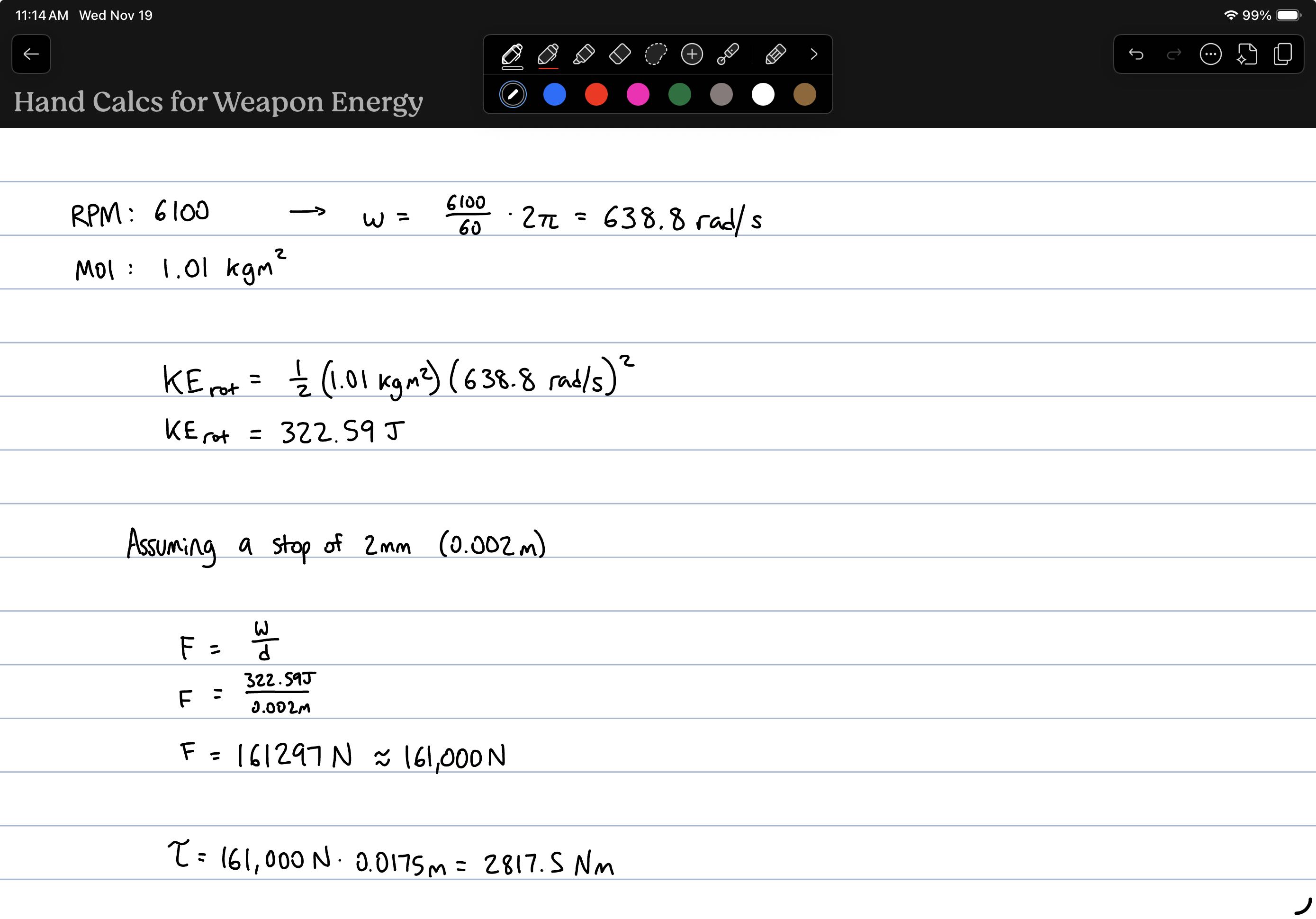
The blade went through several iterations using topology optimization and FEA to improve the stiffness-to-weight ratio. Because combat robotics creates highly unpredictable loads, I also did hand calculations to estimate the forces experienced by the weapon system.
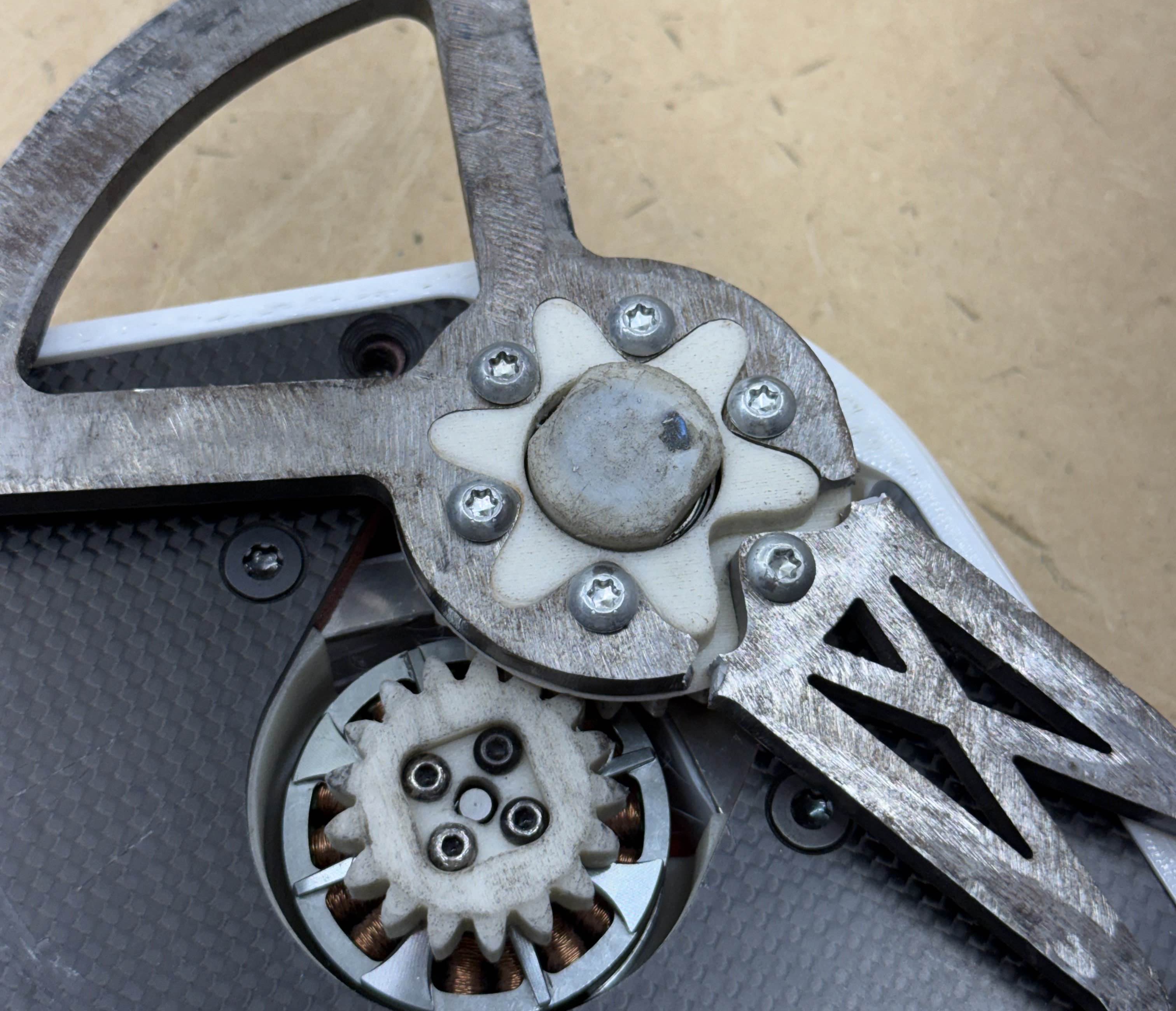
Two of our earliest changes were switching from pulleys to gears and from needle bearings to ball bearings. The pulley on MK1 would melt or fall off during fights, so gears gave us a much more durable drive system. We also switched to ball bearings to provide both radial and axial support for the weapon while reducing friction and dust ingress.
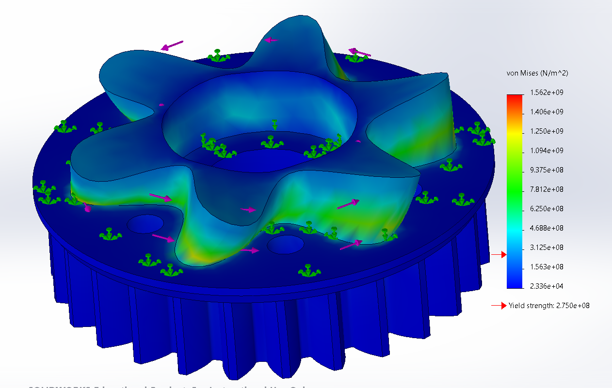
We ran into another issue when the 4x M3 screws holding the gear to the motor started shearing. To fix this, I designed a keying profile that interfaced with the motor's contours and increased the torsional strength of the motor gear assembly.
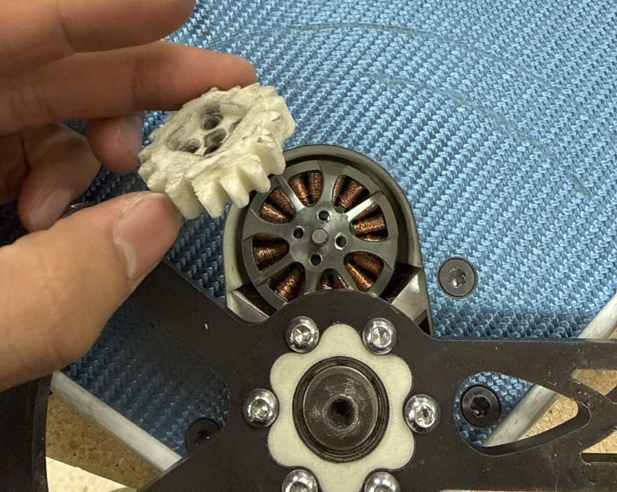
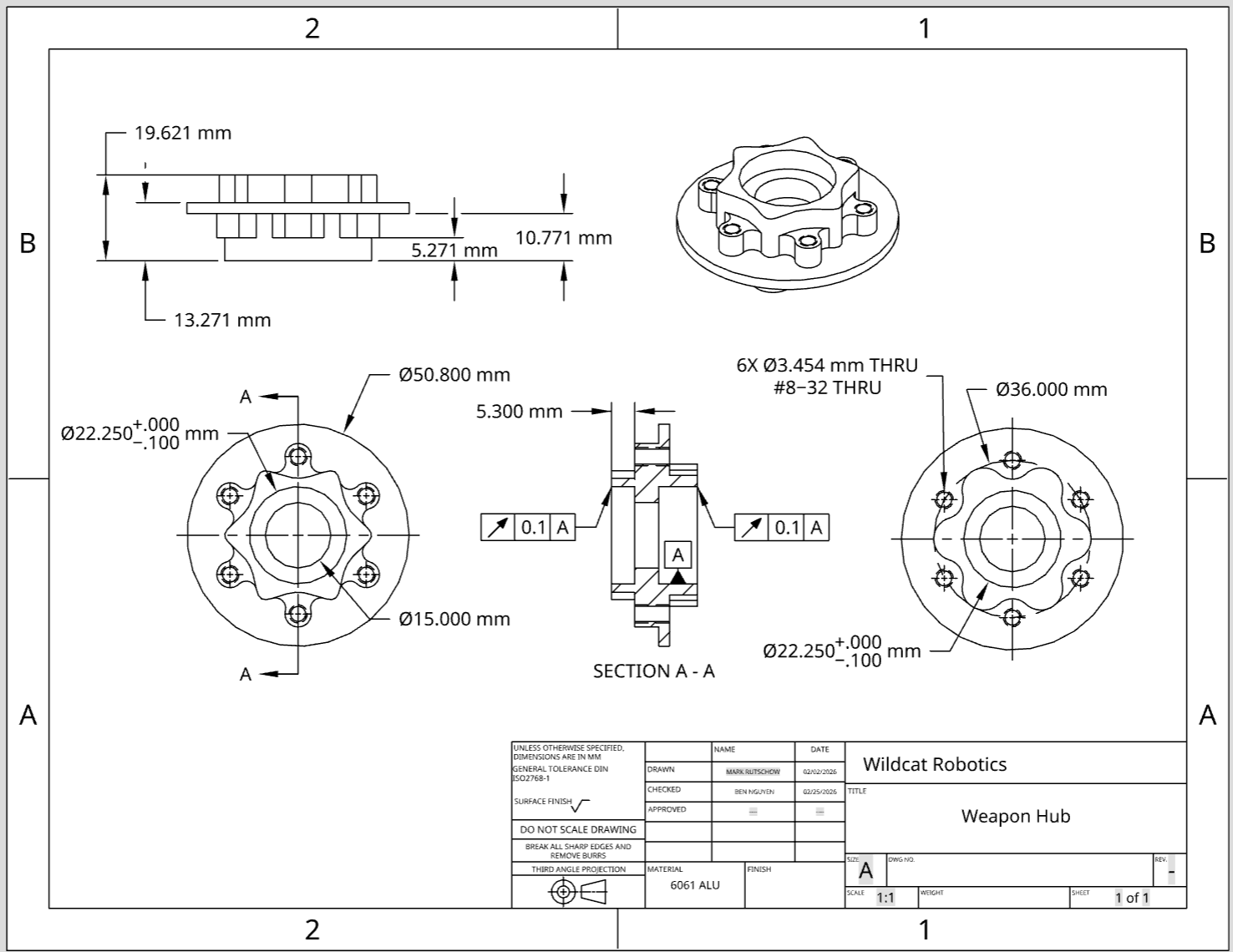
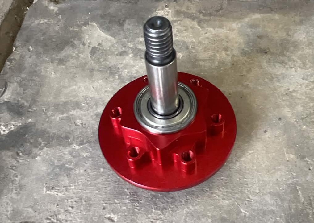
Even after the gear and bearing changes, the 3D-printed weapon hub was still not strong enough. The hub would fail under the normal and shear forces from impacts, causing the blade to fly off. We eventually switched to a CNC-machined 6061 aluminum hub. It has a key profile on both sides so the 3D-printed nylon teeth can still be driven, while the primary load paths run through the aluminum. After making this change, we stopped having weapon failures and the entire system became much more robust.
I created an engineering drawing for the aluminum hub using ASME Y14.5 GD&T and sent it to a manufacturer in China to CNC machine the part. The drawing controlled the critical dimensions and fits so the finished hub would assemble correctly and hold the necessary tolerances.
We also introduced a 3/8" AR500 blade for vertical spinners to reduce deflection on vertical hits and give us more attack options. We could run a longer, thinner blade with more reach, or a shorter, thicker blade that was more durable against vertical attacks.
Drivetrain
We changed the wheels from latex-coated foam to cast urethane wheels around TPU hubs. This dramatically improved both grip and durability. We also upgraded the drive system with more powerful motors and stronger gearboxes.
Electronics
Getting the electronics right was one of the trickiest parts of the project. We dealt with receiver brownouts that caused us to lose connection on big hits, as well as ESCs burning out from excessive current draw.
To fix these issues, we upgraded to more durable drive and weapon ESCs and added capacitors to each ESC to help absorb voltage spikes during impacts. We also added a dedicated BEC instead of powering the receiver from a motor ESC's BEC, giving us redundancy and reducing the chance of losing connection during a hit.
Along the way, I learned proper soldering techniques to make the electrical harness more reliable and added wire-routing channels to reduce strain on the wiring inside the robot.
Chassis
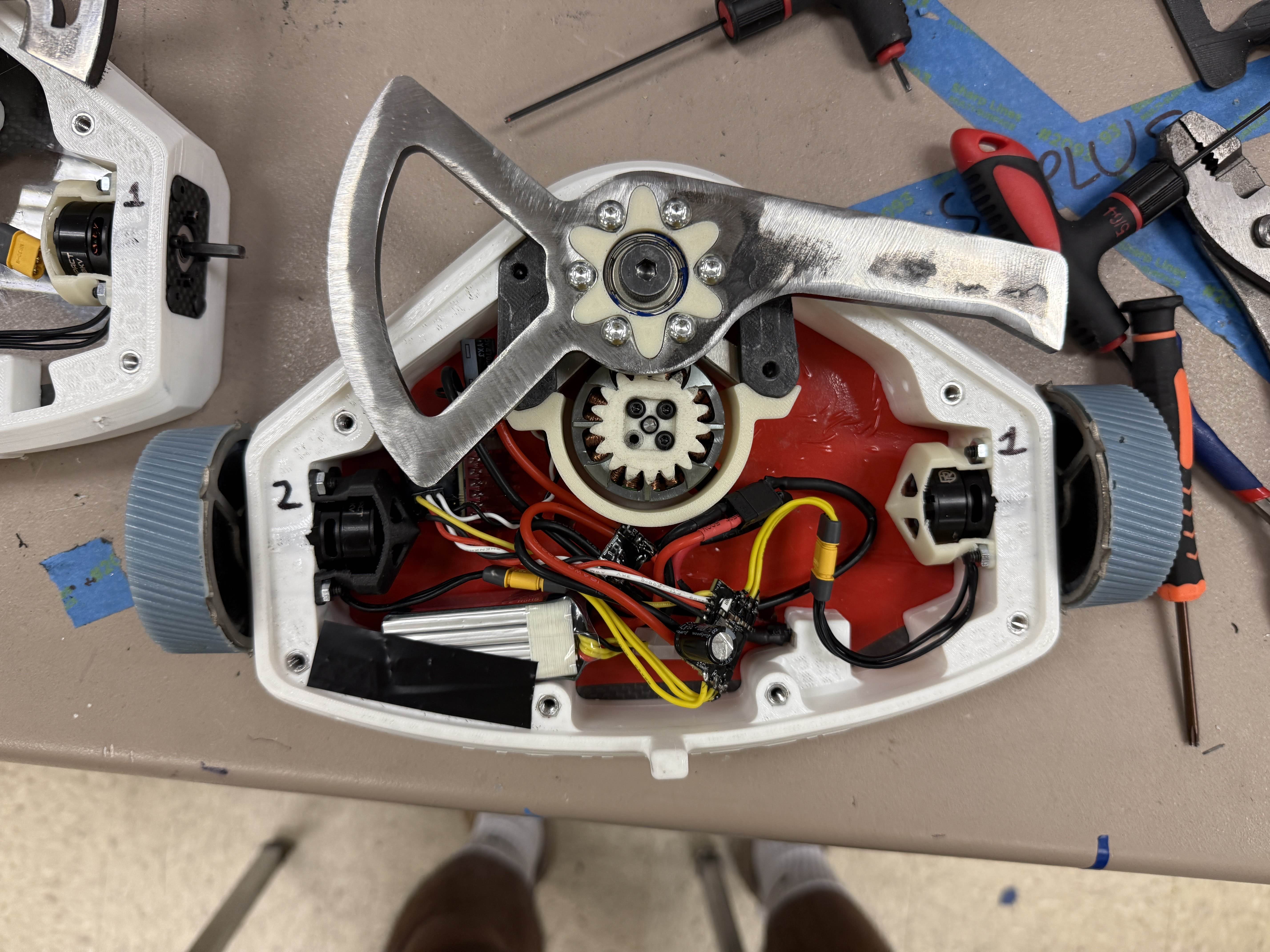
We changed the chassis from milled plastic to 3D-printed TPU with aluminum standoffs holding two carbon fiber plates together. This gave us an ablative, impact-absorbing mid-chassis while the carbon fiber provided a lightweight and rigid structure for the rest of the robot.
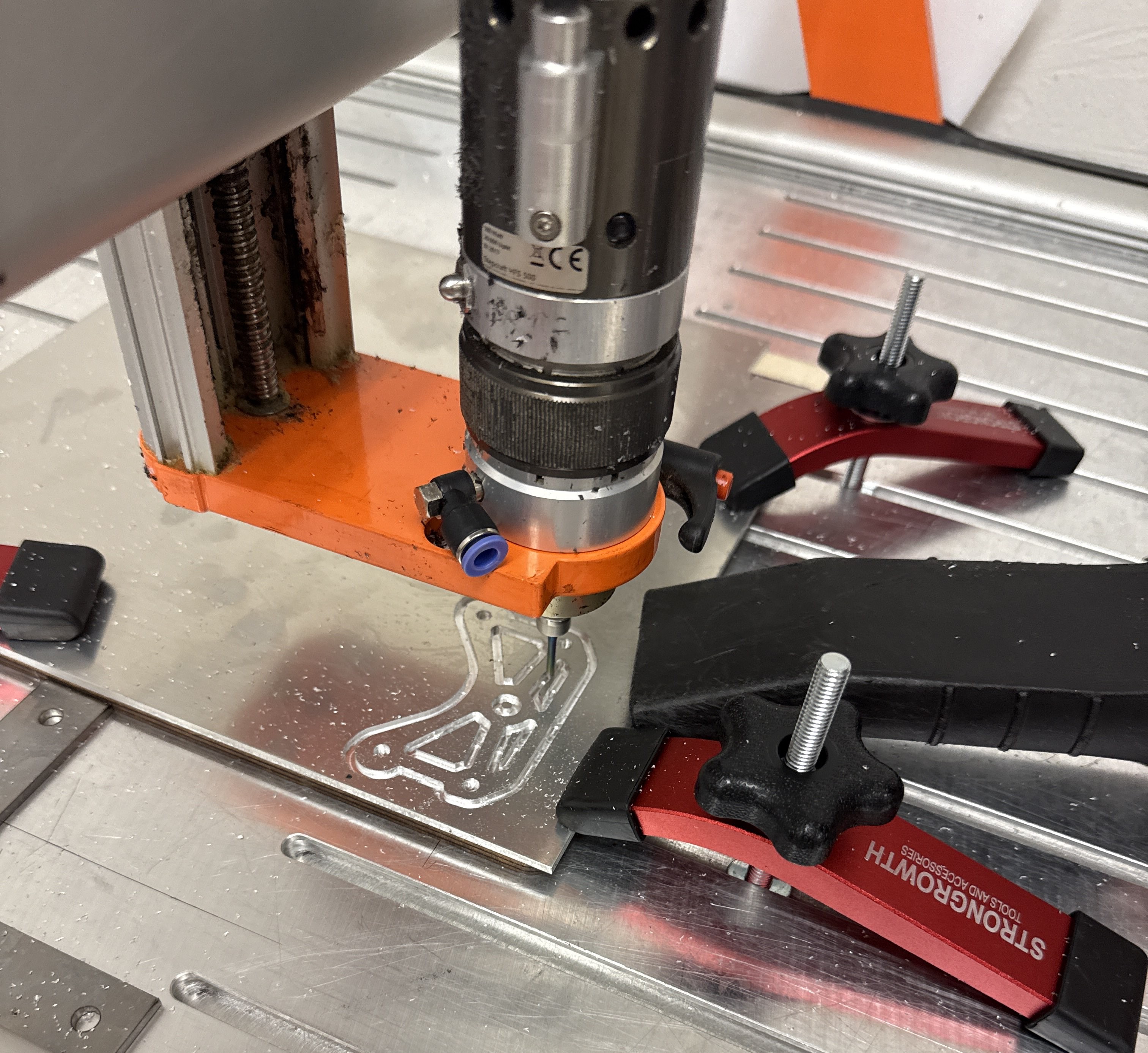
We also redesigned the robot around the manufacturing processes available to us, including 3D printing, laser cutting, CNC routing, and CNC milling. Over time, I fixed many of the assembly issues we had by working directly with the parts and thinking more carefully about how everything needed to fit together.
A lot of our early problems came from simply not knowing what it was like to assemble the robot after designing it. As we gained experience, I put more thought into making the robot intuitive to assemble so that even someone without the same technical background could put it together without making mistakes.
This video describes the changes that I made to improve its repairability.
Outcome
Liberator ended up teaching me more about mechanical engineering than I expected when I first started it. I learned the fundamentals of designing, manufacturing, testing, troubleshooting, and iterating on a real machine, but more importantly, I learned how connected all of those things are. A small design decision could turn into a manufacturing problem, an assembly problem, or a failure in the middle of a competition.
I also learned to become comfortable with things not working the first time. We broke blades, melted belts, sheared screws, burned out ESCs, and rebuilt the robot more times than I can count. Every failure gave us another piece of information that shaped the next version.
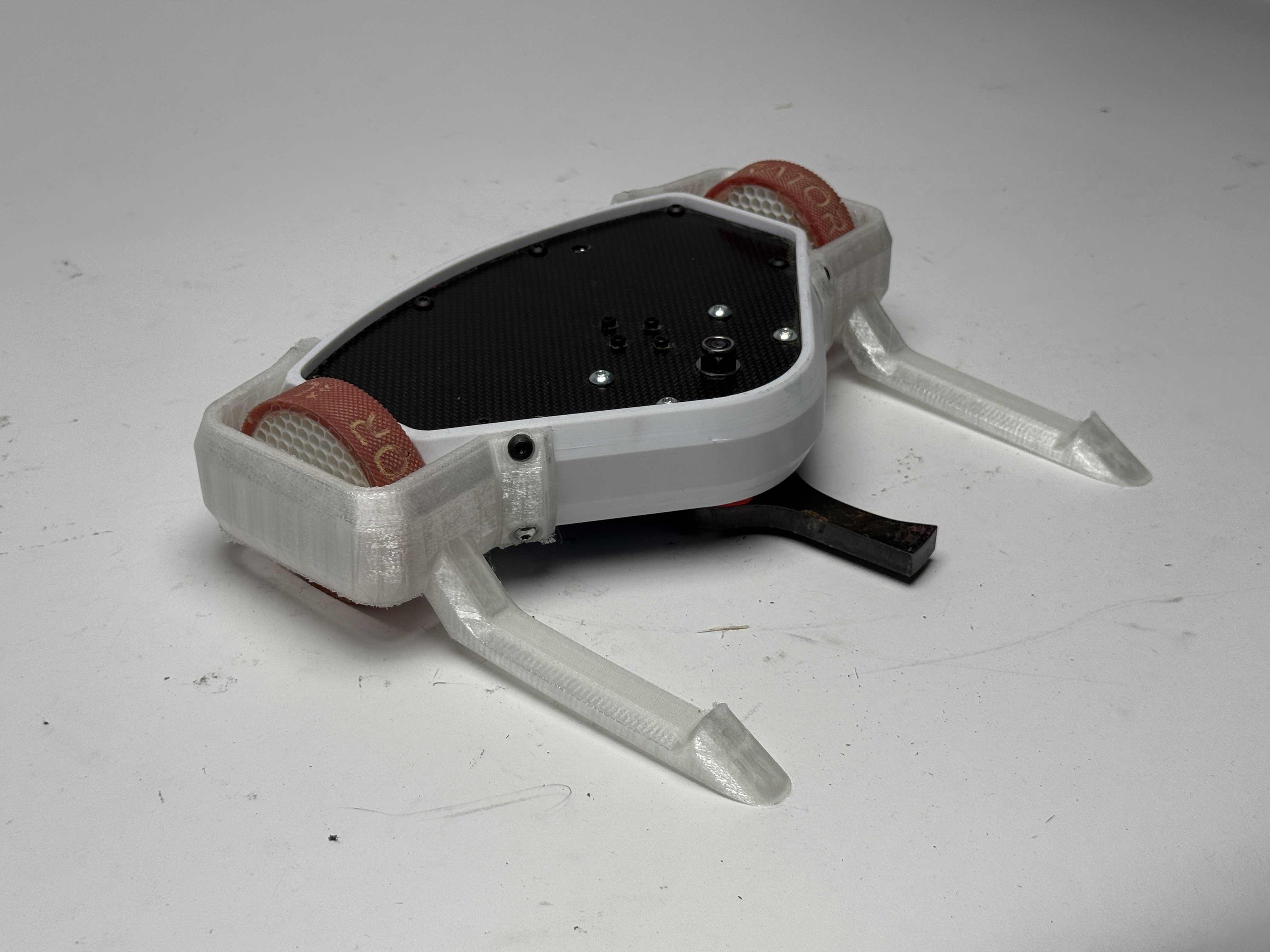
Looking back, Liberator is probably the project that taught me how to actually think like an engineer. It started as a freshman-year robot that I was figuring out as I went, and over several years it became a platform where I could apply everything I was learning in school and through competition. Even though we’ve moved on to bigger projects, I’m still proud of how much this robot and the team behind it grew.