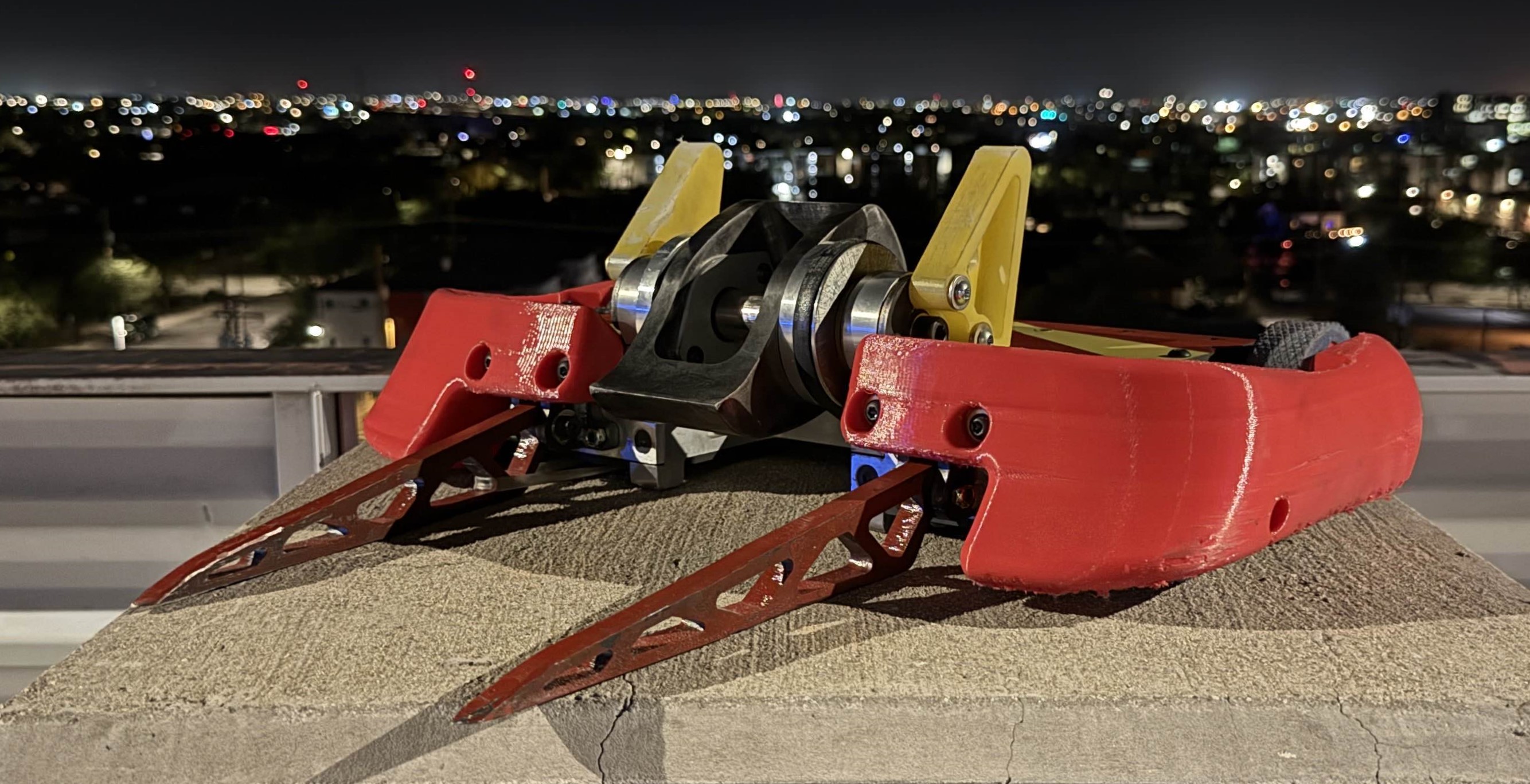
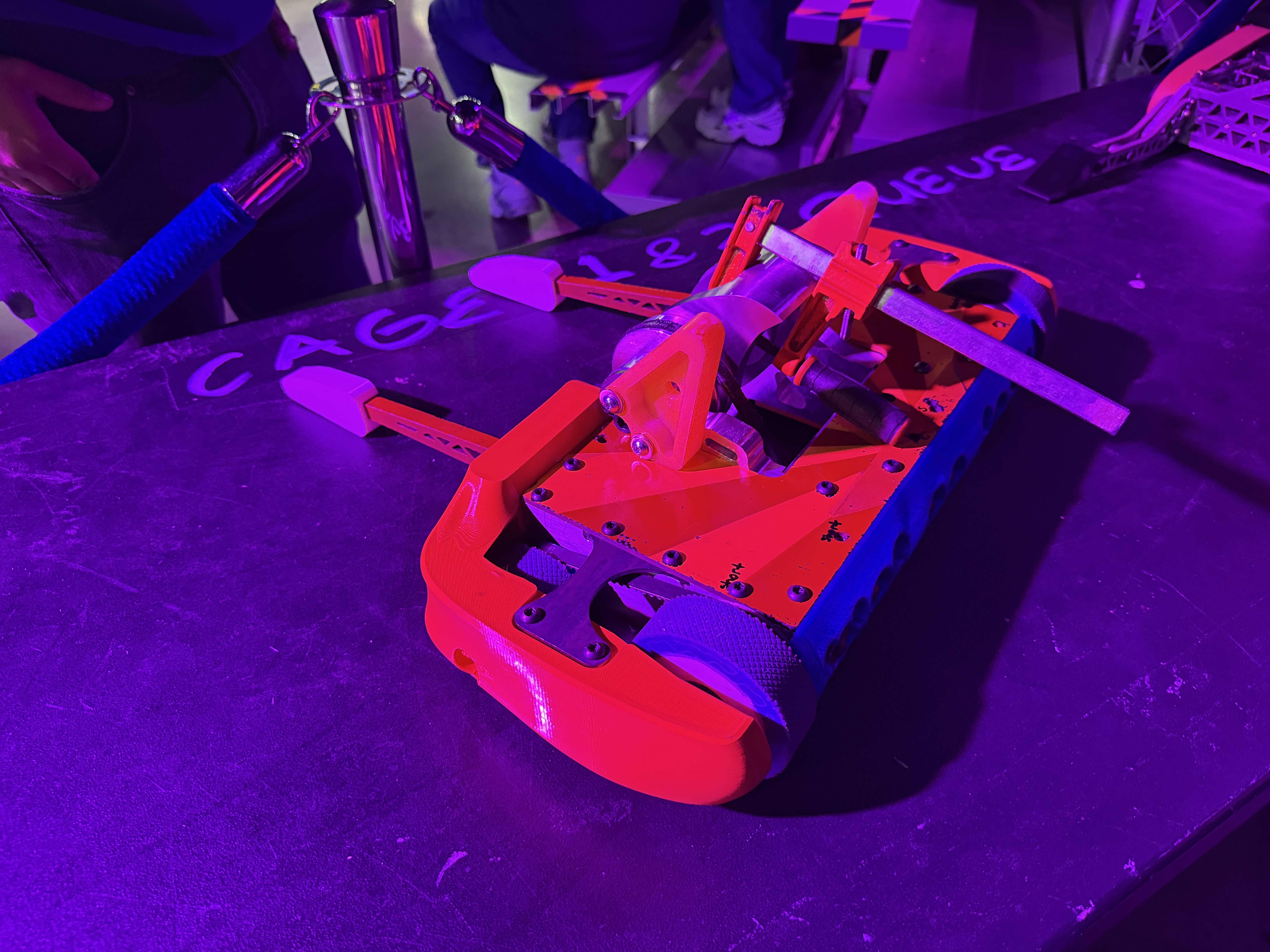
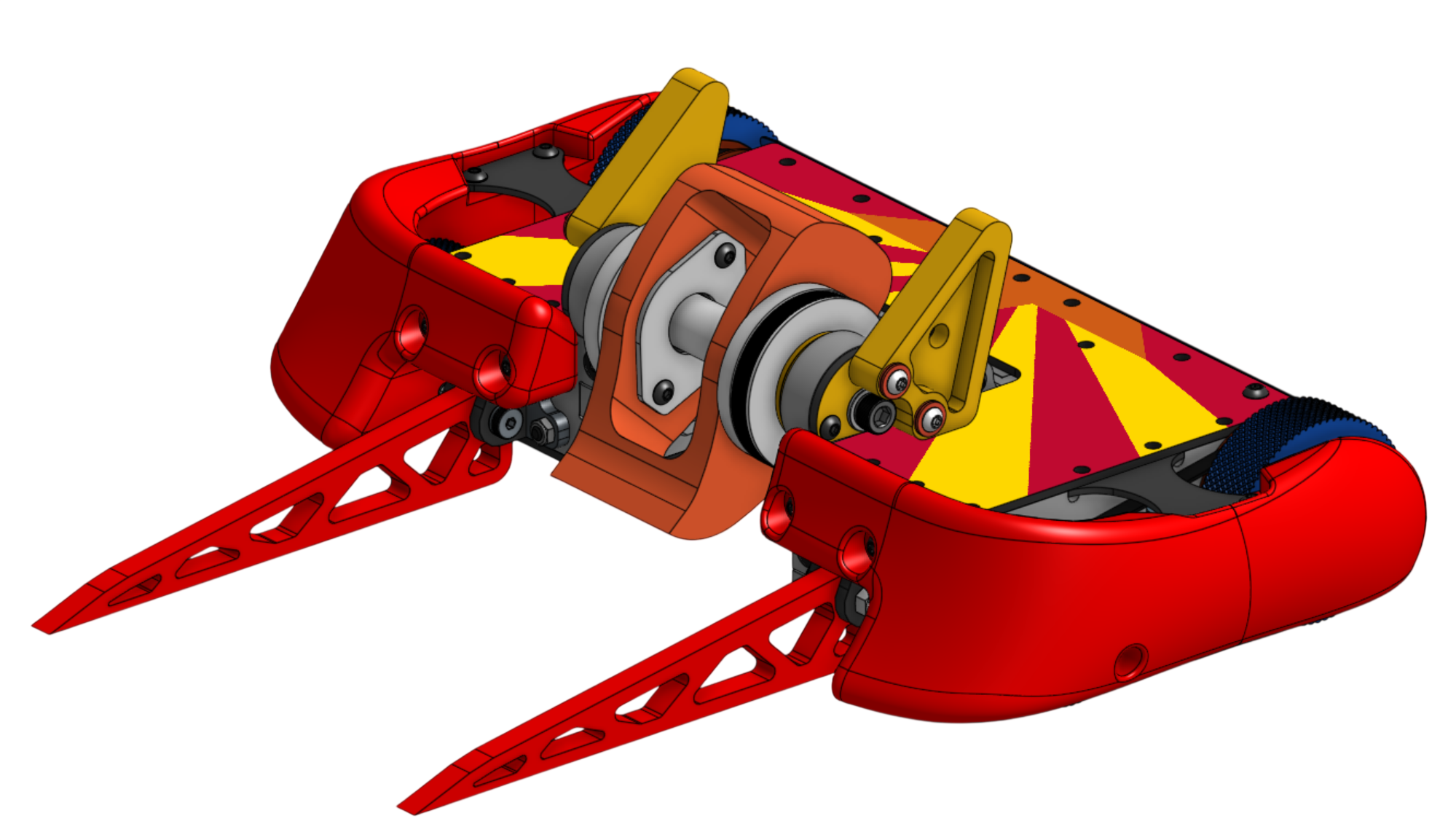
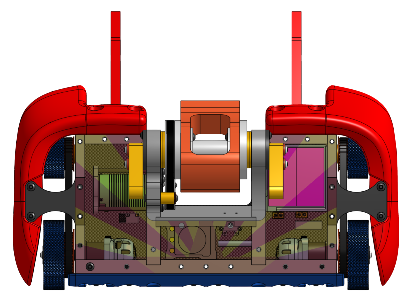
Overview
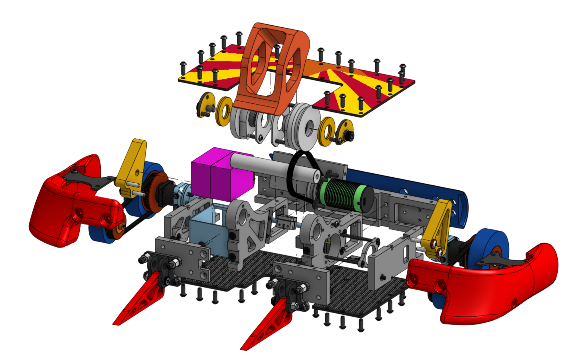
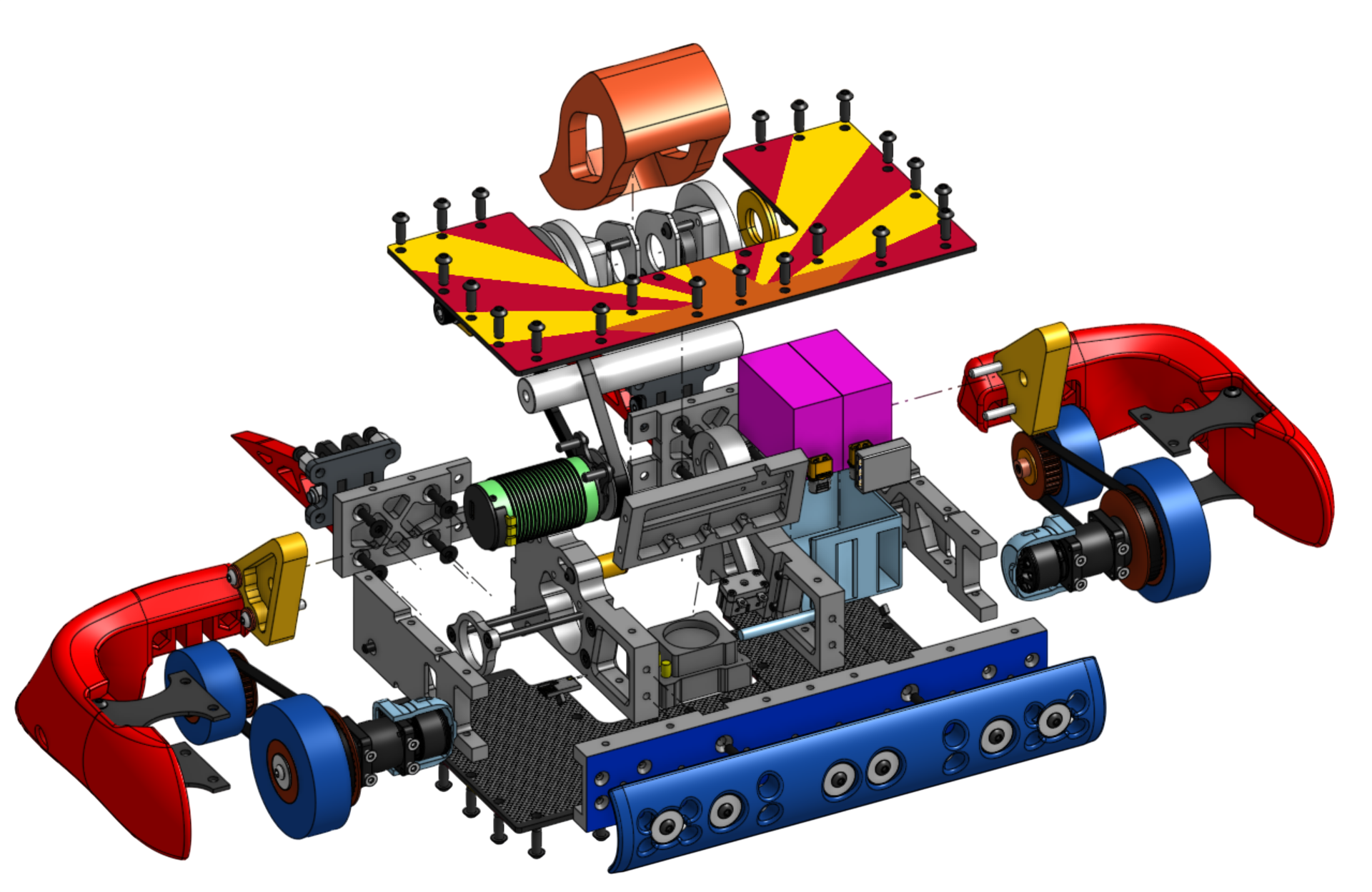
Entering my junior year, I wanted to take on a big, challenging project. Our combat robotics club had only built 3lb bots, so I wanted to scale it up 10x to build a 30lb combat robot. To tackle the challenge, I built a team of 8 mechanical and electrical engineers to design and build the robot from scratch. Over 9 months, we went from concept to CAD to building, testing, and finally competing, with plenty of engineering hurdles along the way. Then I did it all over again for MK2, which we competed with in a national competition in September. We made it to the quarterfinals with a record of 3-1.
Initial Design and Iteration
To start the project, we held several brainstorming sessions to find the most optimal and unique design. After working through a few decision matrices, we settled on a wider robot with a wide, vertically spinning weapon called a beater bar. The wider chassis gives us more control over other robots in the cage since it’s harder to avoid, while also giving us more room for armor attachments. We chose a wide beater bar to increase our damage area compared to a disk weapon. We took inspiration from Ares, Synthesis 30, and Emulsifier, combining the best elements of each.
Once we settled on the overall architecture, it was time to start the CAD. I organized the 8 engineers into teams for drivetrain, weapon, frame, armor, and electrical. I served as the technical and administrative lead, while also being the main contributor to the frame and armor subteams. My responsibilities included scheduling, budgeting, vendor procurement, conflict management, providing feedback on other subsystems, and technical CAD work, including design and analysis.
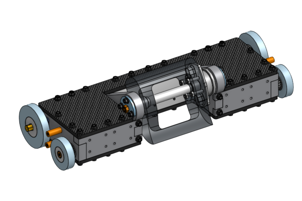
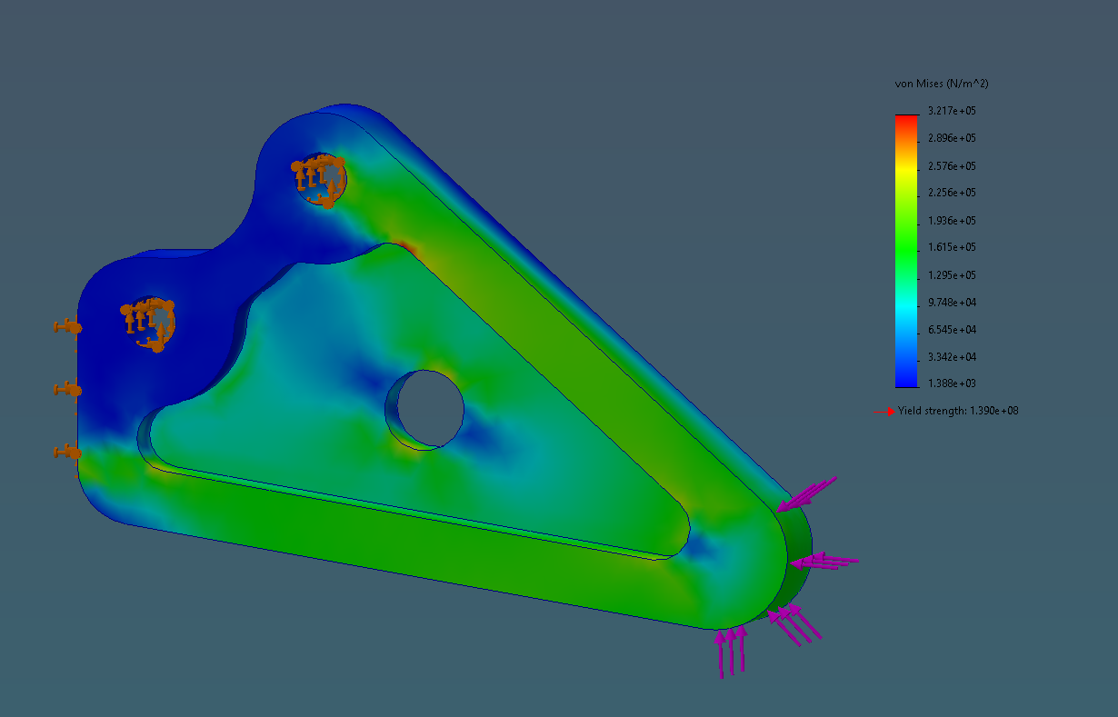
As shown above, we were dramatically overweight, the bot was not structurally sound due to the weak middle section being prone to torsion, and the design was generally not optimized. With the December ordering deadline approaching, the team went into overdrive to fix the CAD and improve each subsystem before placing our orders. We reached out to the combat robotics community for feedback and received a LOT of constructive criticism. Using that feedback, we improved many aspects of the design, including:
Weapon system:
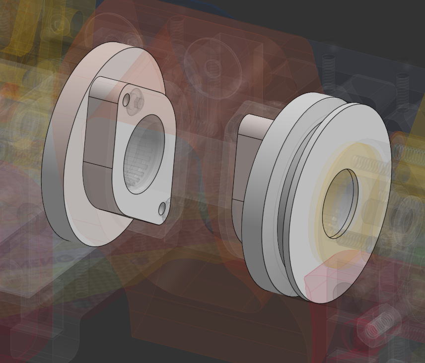
- Increased manufacturability by simplifying geometry, while improving impact robustness through bearing and shaft selection and optimized hub load paths.
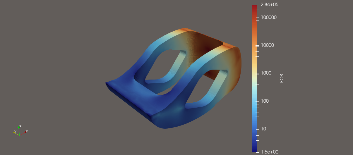
- Reduced weight by redesigning the hubs around a larger keyed interface, reducing the amount of steel in the weapon stack. The 4340 steel beater bar was validated with FEA for both horizontal and vertical impacts. I oversaw the subteam’s design reviews and worked closely with the engineers to implement these changes.
Chassis
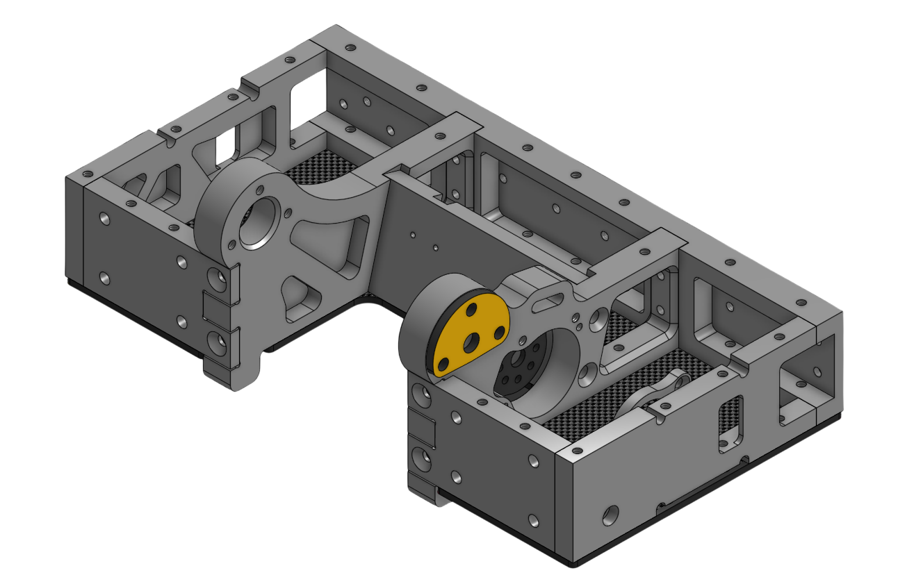
- With the help of my teammate, optimized the frame geometry around our electrical harness.
- Increased serviceability with accessible bolts and modular frame rails.
- Simplified CNC manufacturing to 2.5D operations with minimal setups.
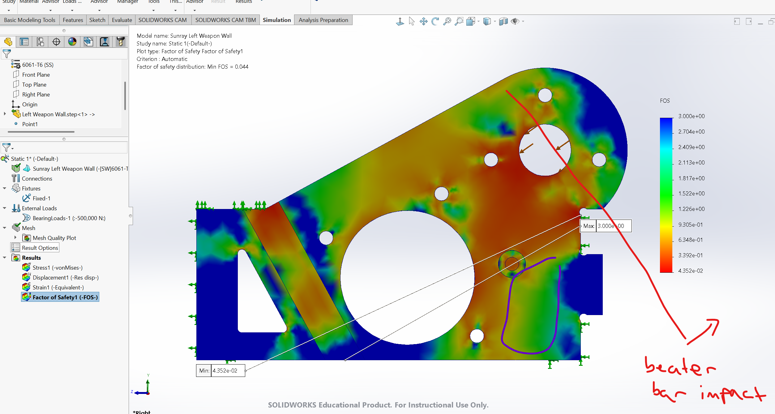
- Ran FEA on the frame rails to validate the pocketing geometry under known loading conditions.
Drivetrain
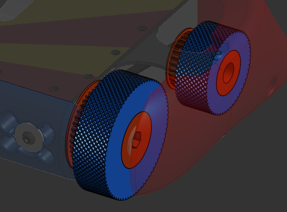
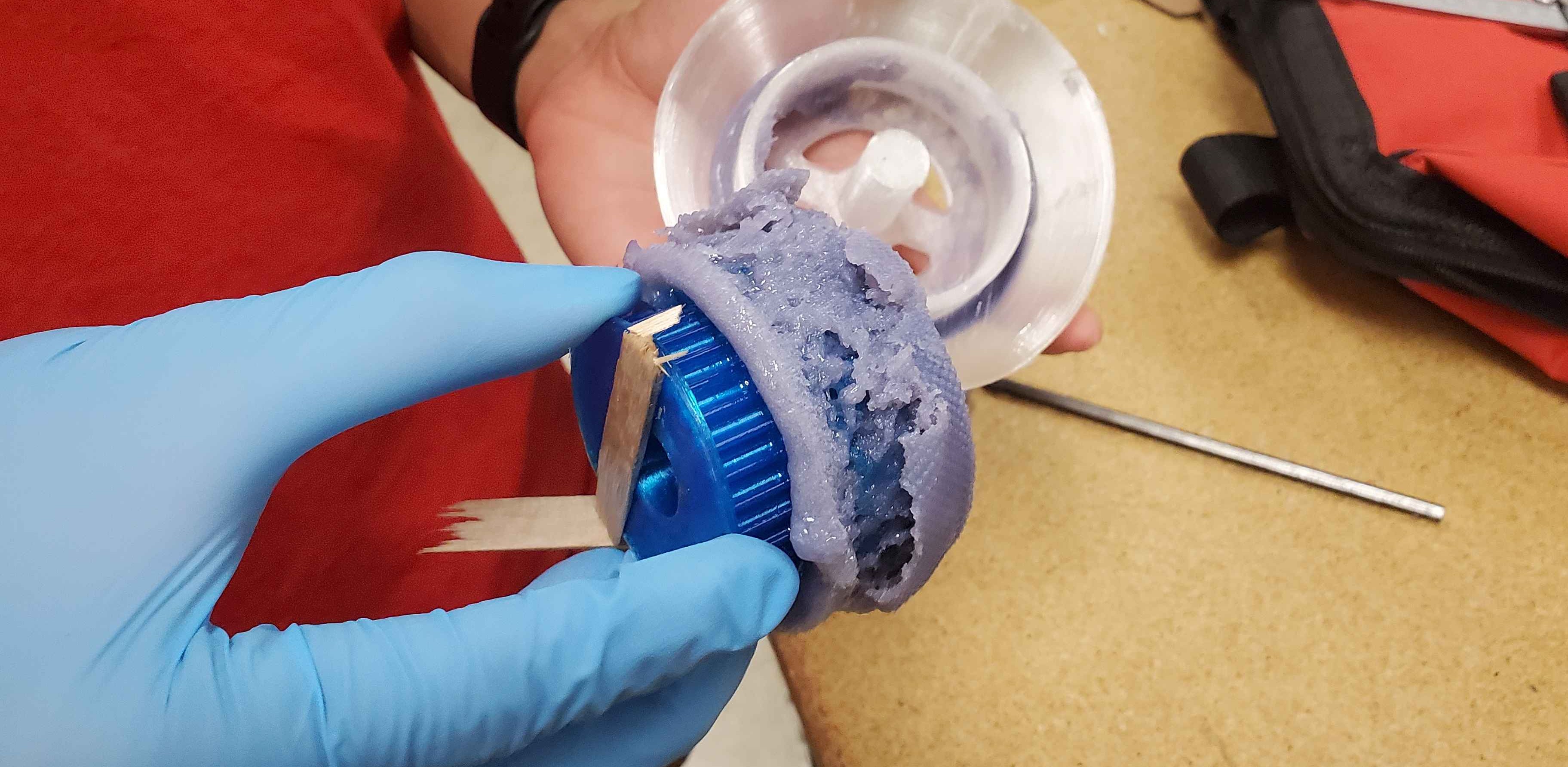
- Selected more robust drive belts, wheel hubs, and bushings to survive the massive forces of combat robotics. I added a knurled tread pattern to reduce dust buildup on the wheels and designed the wheel molds to cast the urethane tires around the TPU wheels.
Armor
- Designed multiple armor configurations to counter different types of robots, including vertical, horizontal, flame, and special-category bots I was the sole contributor to this subteam and challenged myself to create a robust armor package while using advanced surface modeling techniques to give the robot its flowy appearance.
Electrical
The electrical subteam had already selected the components, but I worked with them to optimize the frame layout for wire routing.
Many late nights, design reviews, and team meetings later, we finally finished the design and were able to order our parts.
Manufacturing and Testing
We ordered the hardware and electrical components from third-party suppliers, while external vendors manufactured the flat-cut parts and heat-treated 4340 steel beater bar. Our manufacturing teammate planned to machine the aluminum frame in-house using our HAAS TM-1P CNC mill, which we thought would be ideal since the design and manufacturing teams could work closely together.
To support manufacturing, I created engineering drawings for the weapon and frame using the ASME Y14.5 GD&T standard.
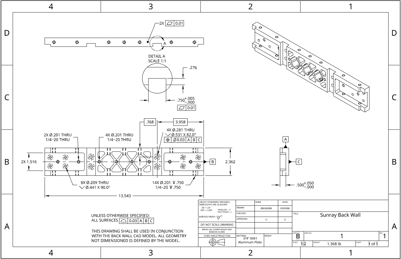
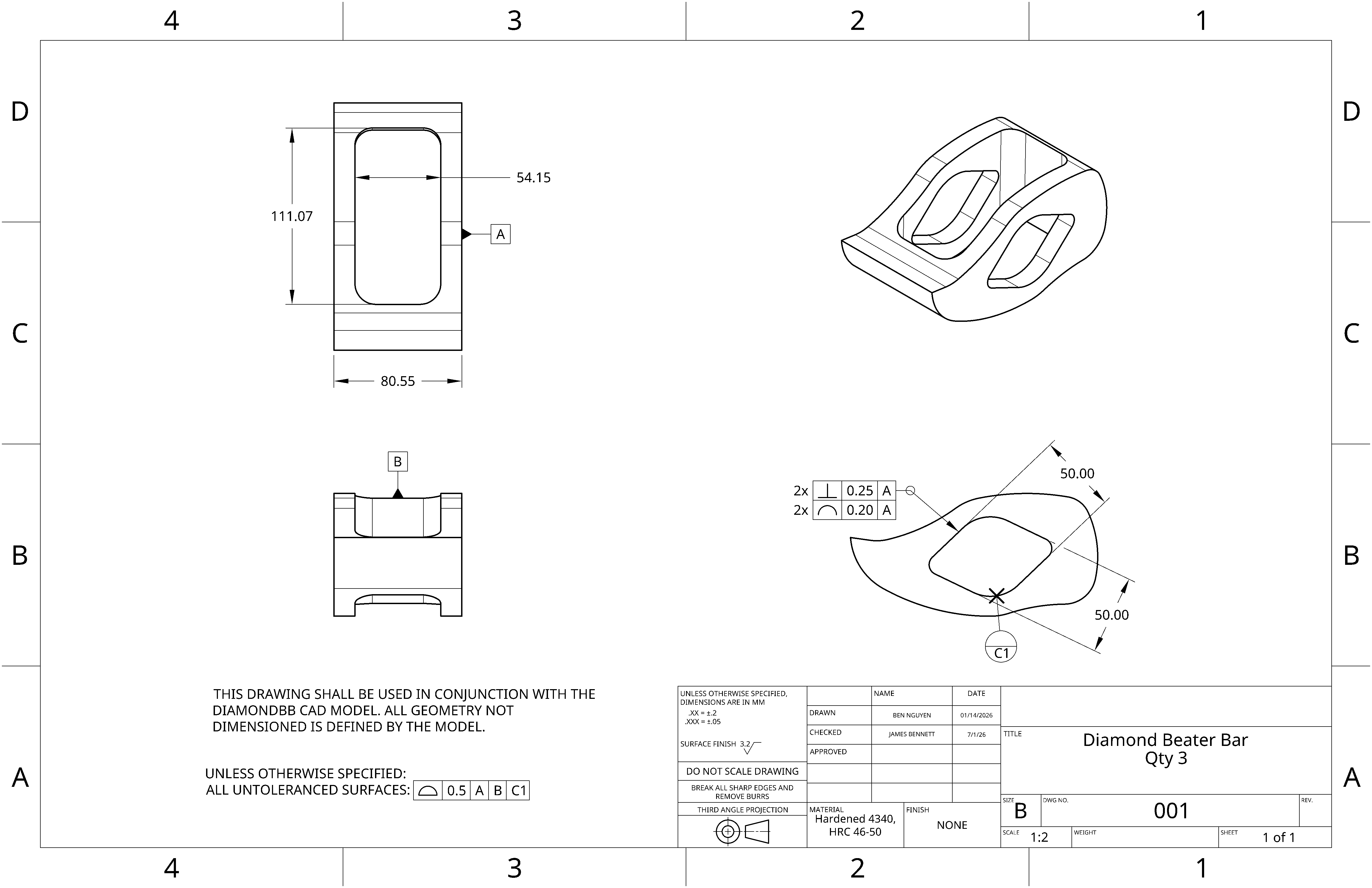
Manufacturing the frame was challenging, with delays from the mill, teammate availability, and setup or G-code errors. Although I wasn’t the one running the CNC mill, working closely with our machinist teammate gave me a much better understanding of where manufacturing could go wrong. With all the delays, we were working up to the last minute before competition to finish the robot. Along the way, we dealt with incorrect mill tolerances, incorrectly dimensioned parts, and unexpected electrical and hardware fitment issues.
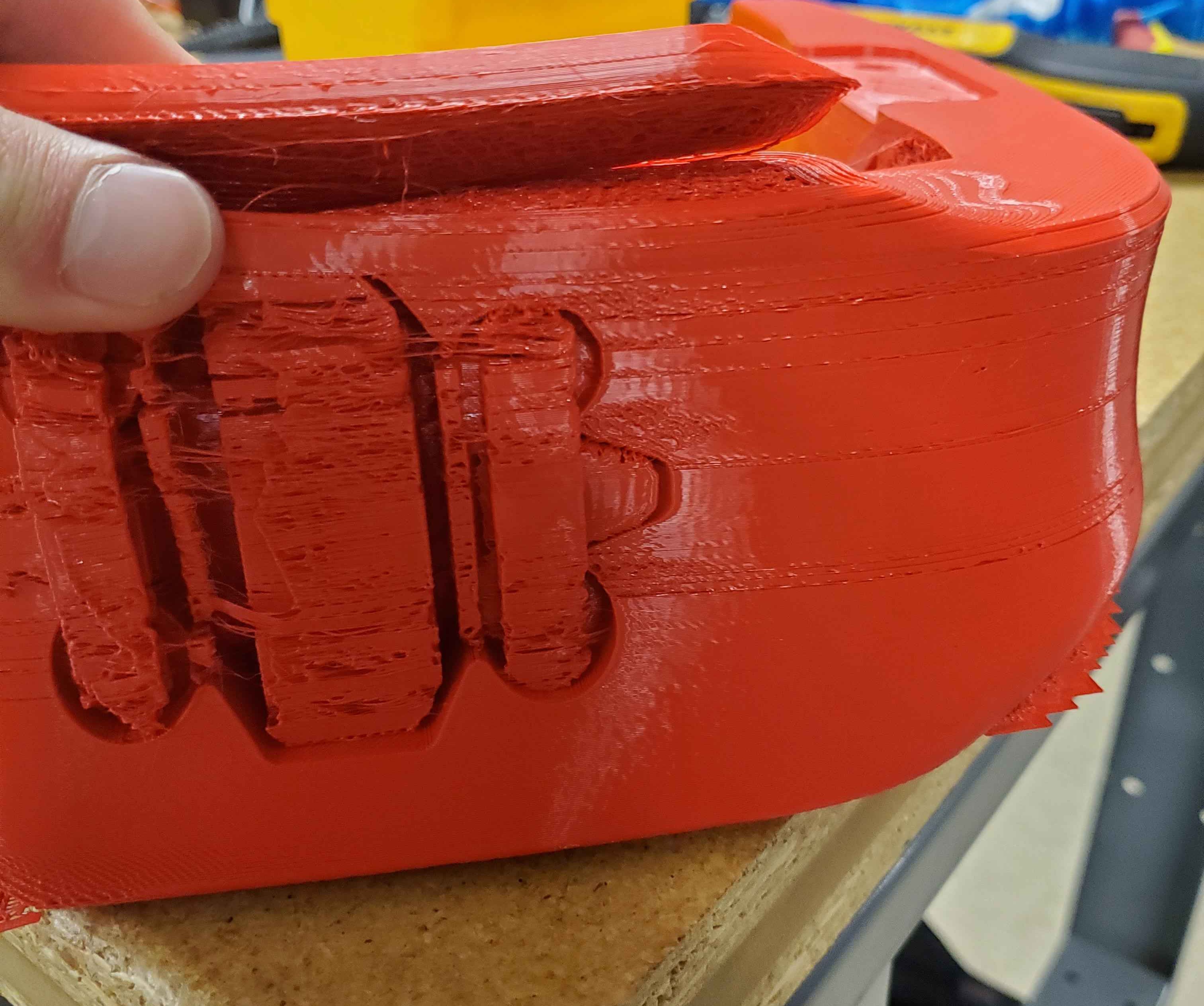
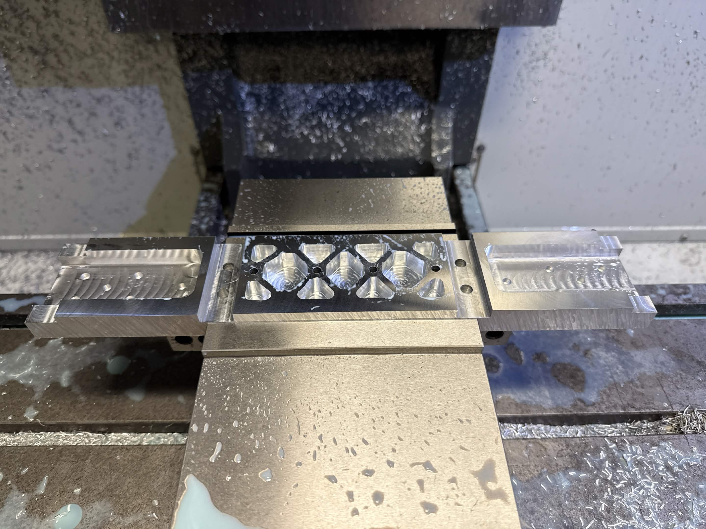
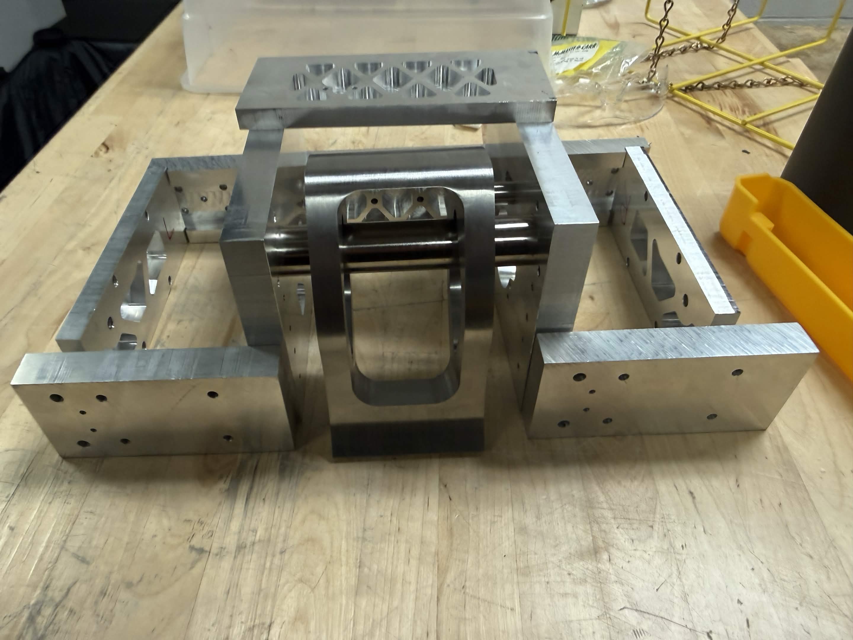
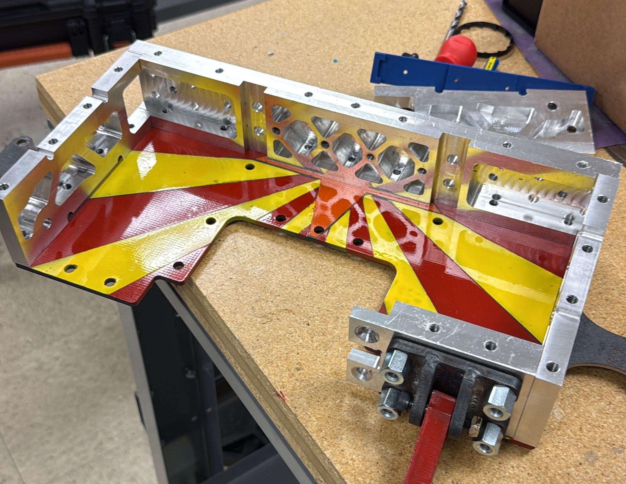
The images below illustrate the manufacturing process (and problems) we had.
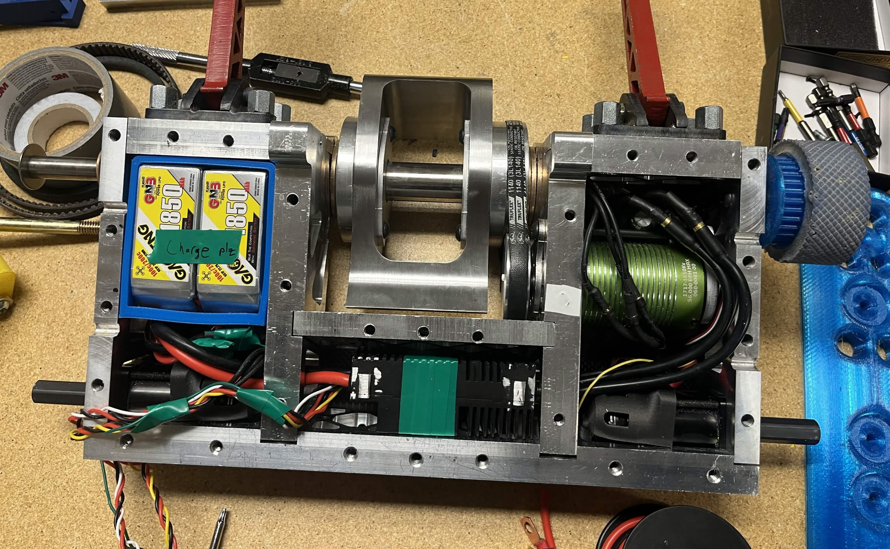
Finally, while assembling and testing the robot, we found several issues. We had CADed the V-belt profile on the pulleys incorrectly, which led to incorrect belt tension and the weapon not being able to spin. The motor pulley was attached using a set screw, and this was extremely weak and fell off every time we spun up the weapon. The weapon ESC tune caused a weak spin-up due to poor pole timing at low speeds. Just before our first fight, we fixed the belt issue by shaving down the belt profile to fit the pulleys. We temporarily fixed the pulley falling off issue by using two set screws like a jam nut to get maximum preload on our set screw. The ESC tuning wasn’t solved until just a few minutes before our first-ever fight, making the whole experience truly down to the wire.
Outcome
Competition #1 (May 2026)
From the late nights in CAD and obsessing over small details, to the struggles of manufacturing, troubleshooting, and testing, to traveling across the country for competition, this project was a roller coaster. We were still preparing the robot until literally the last minute before our fight, and thankfully, some very kind competitors helped us fix our ESC tuning.
We had one fight against Emulsifier, a multi-world champion and one of the bots that inspired our design. Unfortunately, one of our drive wheels seized because we forgot a washer that separated two TPU parts. The parts ended up friction welding together, disabling one side of the drivetrain.
Over those 9 months, I learned how to support my teammates and give them the space to do their best work, while also learning a huge amount about design, manufacturing, and the bridge between the two. It was such a fun journey, and the team saw a lot of potential in the robot. When we were given an invitation to attend an even bigger national tournament in NYC, I couldn't resist the opportunity.
Competition #2 (September 2026)
I decided to go back to the drawing board for MK2. There was a long list of small issues to fix to make the robot more reliable and easier to service. For most of the summer, I spent my evenings redesigning the robot in CAD after my days at my Garmin internship.
I loosened all of the tolerances from our first manufacturing run, and to ensure everything still fit together, I changed the geometry and dimensions of the chassis. I replaced the motor pulley set screw with a clamping hub to fix our attachment issues, and redesigned several frame pieces to reduce weight and improve serviceability. I also worked with the electrical team to select a new sensored motor ESC for better weapon spin-up, which I designed the new chassis around. Finally, I redesigned the AR500 armor packages to counter a wider range of robots, which required me to design the parts for welding.
While making these changes, I mentored one of my teammates into becoming team lead after I left, helping the team continue without me. This taught me a lot about succession planning and documentation.
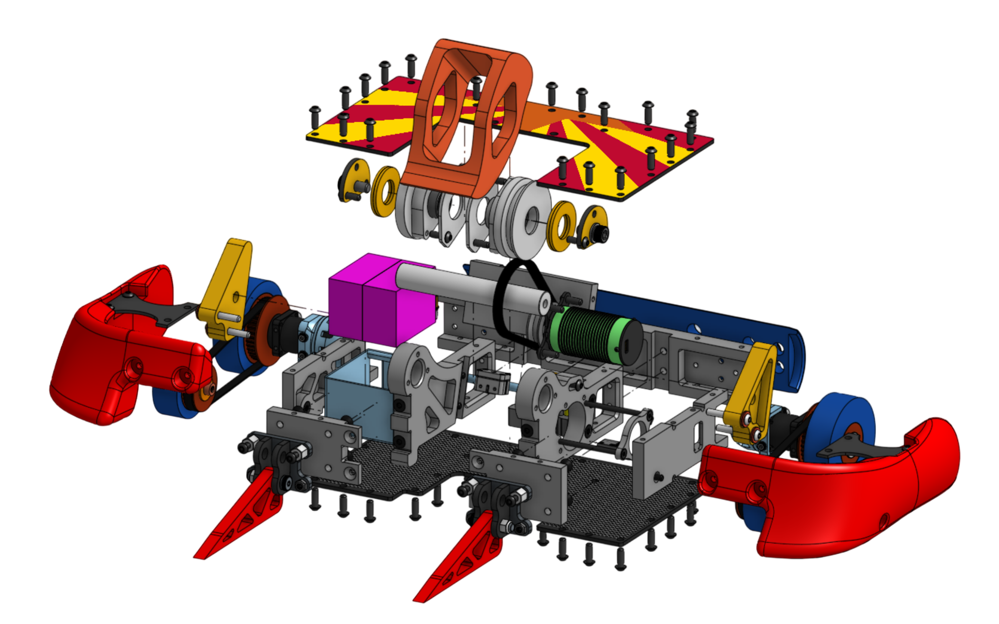
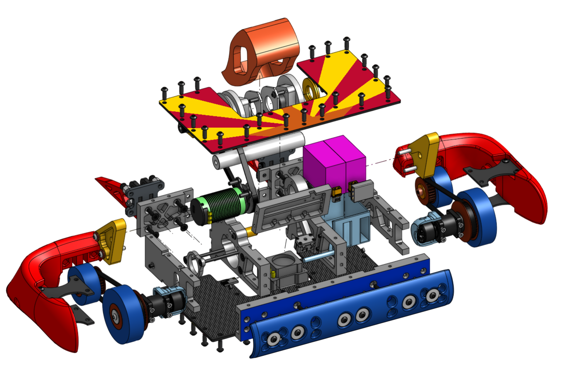
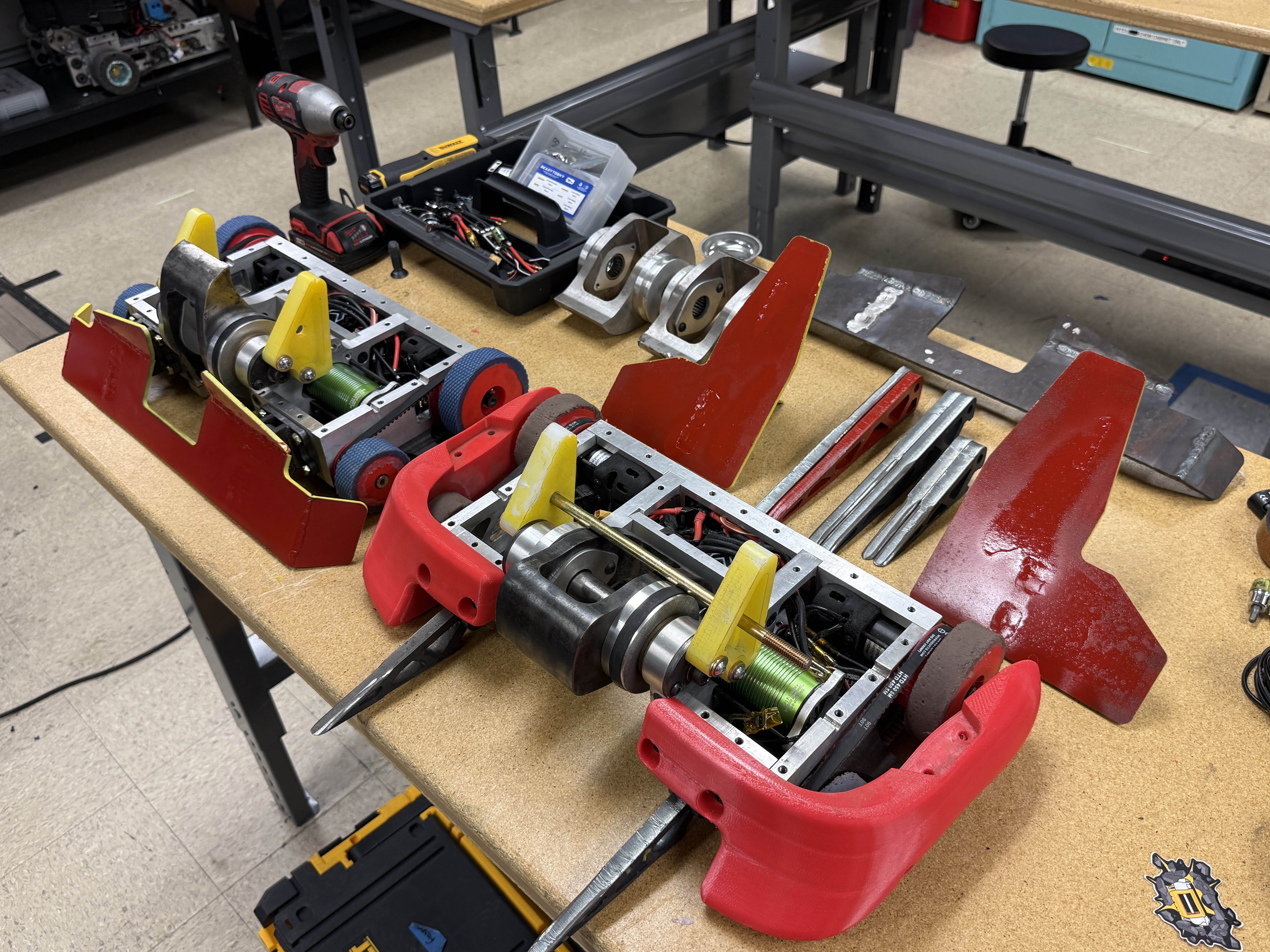
We got the bot together two weeks before competition, and all of the parts fit without any issues. During those two weeks, we tested the drive and weapon. This included tuning the weapon ESC for adequate spin-up and testing the robot's gyroscopic precession while driving.
While testing the weapon ESC, we noticed that the weapon motor temperature climbed rapidly at high throttle. To fix this, I designed an active cooling shroud using two maintenance holes on the chassis as the inlet and exhaust ducts. I used two 35x35x10 fans to blow air onto the side of the motor can and shock mounted them with a floating TPU housing to reduce impact forces inside the robot. I used surface modeling to create smooth curves in the air duct, and it was a fun CAD challenge to retrofit the existing chassis for active cooling.
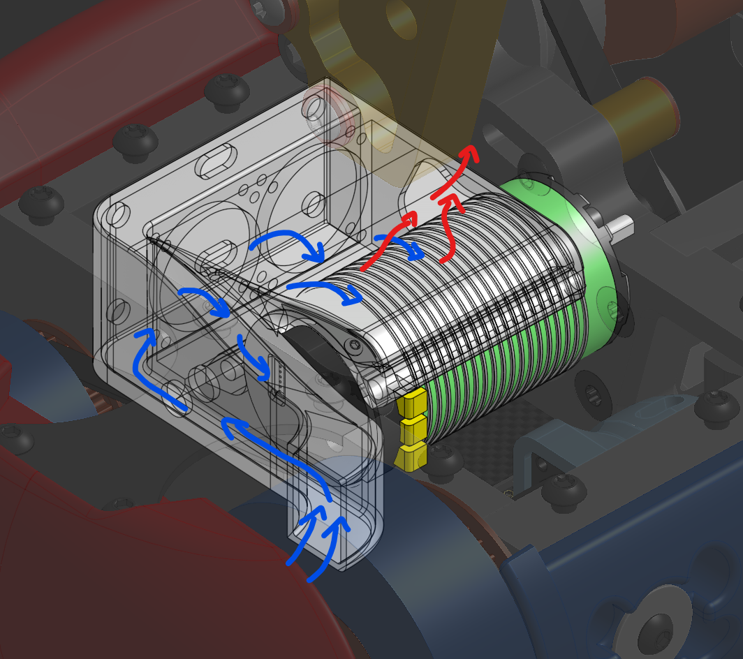
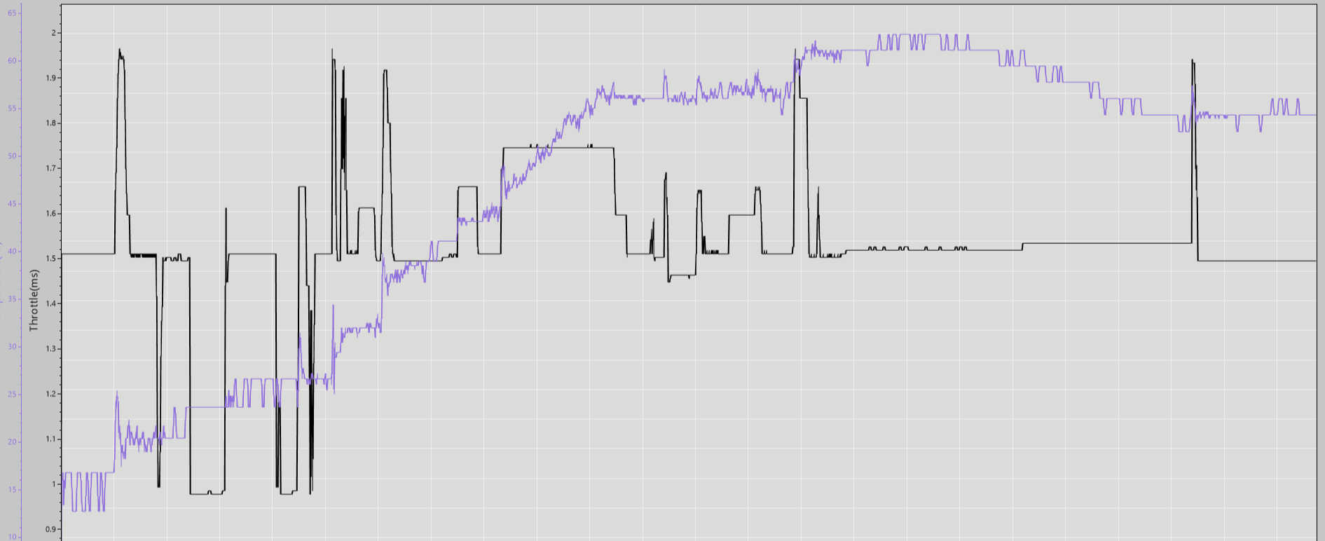
Because the cooling system was retrofitted, the airflow path and inlet and exhaust sizes were not optimal. For the next iteration of Sunray, we will use more direct airflow paths and larger inlet and exhaust ducts to improve motor cooling and allow us to outperform other robots.
Going into the competition, we felt more prepared than last time, but the opponents were more intimidating because it was an invitation-only event. We ended up doing significantly better than we expected, going undefeated (3-0) in the group stage. The new armor configurations worked well, and the robot's electronics were flawless. We won most weapon-on-weapon hits and dealt enough damage to win the fights. Unfortunately, we lost in the bracket after our front horizontal wedge armor bent on a big hit, high-centering the drivetrain and reducing mobility.
We were extremely happy with the result. We were able to beat much more experienced competitors, and the team is excited to keep iterating on the robot. I'll be moving into a mentorship role to focus on other projects, while my teammate takes over team leadership. Building Sunray and leading the team taught me a lot about engineering and working with a team, and it was rewarding to see the countless late nights and problems we worked through pay off.